Site Logo Home
 
rOm
Quest
Glossary
 
Random
Page
Search
Site
Lush
Sim
Class
Subject
Images
 
Help
FAQ
Sign
Up
Log
In
A Level     Signal     ADC Flash     ADC Ramp     DAC Summing     >Distortion<     Problems     Regenerator     Sample and Hold     Sampling     Serial and Parallel     signal to noise ratio    

Signal Distortion


Site for Eduqas/WJEC - Go to the AQA site.

  A Level    Signals  0 of 24    Question 1419    Cable Length Limits 
Score 0/0 
Not attempted  
Last Answer  
Deadline not set1 of 24    Question 1418    Cable Length Limits 
Score 0/0 
Not attempted  
Last Answer  
Deadline not set2 of 24    Question 1417    Cable Length Limits 
Score 0/0 
Not attempted  
Last Answer  
Deadline not set3 of 24    Question 835    Cable Length Limits 
Score 0/0 
Not attempted  
Last Answer  
Deadline not set4 of 24    Question 834    Cable Length Limits 
Score 0/0 
Not attempted  
Last Answer  
Deadline not set5 of 24    Question 833    Cable Length Limits 
Score 0/0 
Not attempted  
Last Answer  
Deadline not set6 of 24    Question 832    Cable Length Limits 
Score 0/0 
Not attempted  
Last Answer  
Deadline not set7 of 24    Question 793    Celular Networks 
Score 0/0 
Not attempted  
Last Answer  
Deadline not set8 of 24    Question 800    Celular Networks 
Score 0/0 
Not attempted  
Last Answer  
Deadline not set9 of 24    Question 684    Sampling 
Score 0/0 
Not attempted  
Last Answer  
Deadline not set10 of 24    Question 686    Sampling 
Score 0/0 
Not attempted  
Last Answer  
Deadline not set11 of 24    Question 816    Serial and Parallel Data 
Score 0/0 
Not attempted  
Last Answer  
Deadline not set12 of 24    Question 817    Serial and Parallel Data 
Score 0/0 
Not attempted  
Last Answer  
Deadline not set13 of 24    Question 818    Serial and Parallel Data 
Score 0/0 
Not attempted  
Last Answer  
Deadline not set14 of 24    Question 819    Serial and Parallel Data 
Score 0/0 
Not attempted  
Last Answer  
Deadline not set15 of 24    Question 820    Serial and Parallel Data 
Score 0/0 
Not attempted  
Last Answer  
Deadline not set16 of 24    Question 821    Serial and Parallel Data 
Score 0/0 
Not attempted  
Last Answer  
Deadline not set17 of 24    Question 822    Serial and Parallel Data 
Score 0/0 
Not attempted  
Last Answer  
Deadline not set18 of 24    Question 823    Serial and Parallel Data 
Score 0/0 
Not attempted  
Last Answer  
Deadline not set19 of 24    Question 815    Serial and Parallel Data 
Score 0/0 
Not attempted  
Last Answer  
Deadline not set20 of 24    Question 814    Serial and Parallel Data 
Score 0/0 
Not attempted  
Last Answer  
Deadline not set21 of 24    Question 813    Serial and Parallel Data 
Score 0/0 
Not attempted  
Last Answer  
Deadline not set22 of 24    Question 812    Serial and Parallel Data 
Score 0/0 
Not attempted  
Last Answer  
Deadline not set23 of 24    Question 811    Serial and Parallel Data 
Score 0/0 
Not attempted  
Last Answer  
Deadline not set24 of 24    Question 309    Sub-systems 
Score 0/0 
Not attempted  
Last Answer  
Deadline not set  Questions 0 to 24   -->  View All  

In an ideal world, electronic circuits would process signals perfectly.
In real life, circuits introduce errors in the output called DISTORTION.
Well designed circuits minimise distortion.
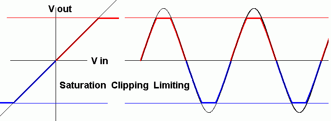
Clipping, Limiting or Saturation

Clipping, Limiting or Saturation

Cross-Over Distortion

Cross over distortion happens when the input signal is so small that neither device in a push-pull amplifier is turned on. Low input voltages are missing from the output. This can be reduced by BIASING the amplifier MOSFETS and by adding NEGATIVE FEEDBACK to the circuit.
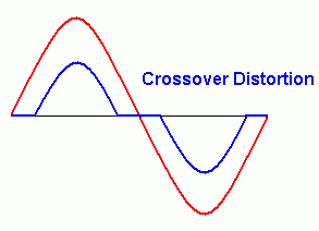
Cross Over Distortion

Non-Linearity

The red wave is what the amplifier should produce. The blue wave is distorted from the wanted shape. There is no clipping. The low input levels are not damaged. NEGATIVE FEEDBACK greatly reduces this type of distortion.
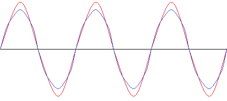
Distortion due to non-linearity

Output Slew Rate Problems

Amplifiers have an upper limit to the rate at which the output can rise or fall. This is called the slew rate.

A sudden input voltage change will cause a less sudden output change. Even sine wave inputs can be damaged. The output tries but fails to keep up with the input changes.

This is somewhat like the 0 to 60 performance figure for a car. If you "floor" the accelerator, it still takes time for the car to build up speed.

Biasing and negative feedback don't help.

The only fix is to use devices with a higher slew rate. Both signals in the diagram below are distorted due to the slow output slew rate.
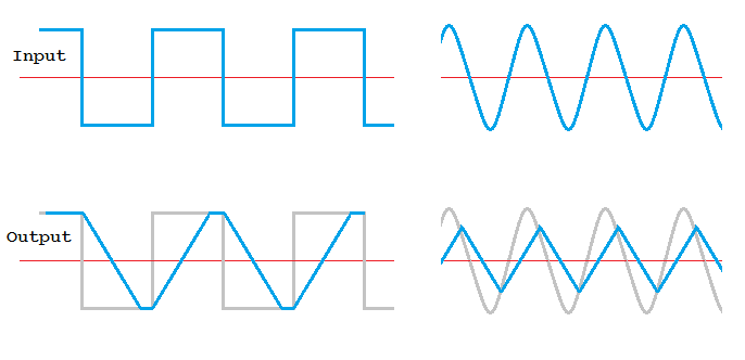
Slew Rate Examples

Don't confuse Distortion with Noise

Distortion occurs when circuits don't reproduce input signals perfectly.

Noise comes from external sources or sometimes from the circuit itself because it's warm. This warmth causes random atom vibrations along with the electrons. This random electron movement, if amplified, appears as a hissing noise in the output.

Subject Name     Level     Topic Name     Question Heading     First Name Last Name Class ID     User ID    

fff
Home
<<<
ppw
Pg Up
<<
ppp
Up
<
|||

>|<
nnn
Down
>
nnw
Pg Down
>>
lll
End
>>>

Close
Escape
X

Q: qNum of last_q     Q ID: Question ID         Score: num correct/num attempts         Date Done    


Submit
Enter


Question Text

image url


Help Link

Add     Delete     Clone     Edit     Hardness

Help Text
Debug


Contact, Copyright, Cookies and Legalities: C Neil Bauers - reviseOmatic V4 - © 2016/17

Hosted at linode.com - London


Please report website problems to Neil