Site Logo Home
 
rOm
Quest
Glossary
 
Random
Page
Search
Site
Lush
Sim
Class
Subject
Images
 
Help
FAQ
Sign
Up
Log
In
A Level     Signal     ADC Flash     ADC Ramp     >DAC Summing<     Distortion     Problems     Regenerator     Sample and Hold     Sampling     Serial and Parallel     signal to noise ratio    

Signal DAC Summing


Site for Eduqas/WJEC - Go to the AQA site.

  A Level    Signals  0 of 24    Question 1419    Cable Length Limits 
Score 0/0 
Not attempted  
Last Answer  
Deadline not set1 of 24    Question 1418    Cable Length Limits 
Score 0/0 
Not attempted  
Last Answer  
Deadline not set2 of 24    Question 1417    Cable Length Limits 
Score 0/0 
Not attempted  
Last Answer  
Deadline not set3 of 24    Question 835    Cable Length Limits 
Score 0/0 
Not attempted  
Last Answer  
Deadline not set4 of 24    Question 834    Cable Length Limits 
Score 0/0 
Not attempted  
Last Answer  
Deadline not set5 of 24    Question 833    Cable Length Limits 
Score 0/0 
Not attempted  
Last Answer  
Deadline not set6 of 24    Question 832    Cable Length Limits 
Score 0/0 
Not attempted  
Last Answer  
Deadline not set7 of 24    Question 793    Celular Networks 
Score 0/0 
Not attempted  
Last Answer  
Deadline not set8 of 24    Question 800    Celular Networks 
Score 0/0 
Not attempted  
Last Answer  
Deadline not set9 of 24    Question 684    Sampling 
Score 0/0 
Not attempted  
Last Answer  
Deadline not set10 of 24    Question 686    Sampling 
Score 0/0 
Not attempted  
Last Answer  
Deadline not set11 of 24    Question 816    Serial and Parallel Data 
Score 0/0 
Not attempted  
Last Answer  
Deadline not set12 of 24    Question 817    Serial and Parallel Data 
Score 0/0 
Not attempted  
Last Answer  
Deadline not set13 of 24    Question 818    Serial and Parallel Data 
Score 0/0 
Not attempted  
Last Answer  
Deadline not set14 of 24    Question 819    Serial and Parallel Data 
Score 0/0 
Not attempted  
Last Answer  
Deadline not set15 of 24    Question 820    Serial and Parallel Data 
Score 0/0 
Not attempted  
Last Answer  
Deadline not set16 of 24    Question 821    Serial and Parallel Data 
Score 0/0 
Not attempted  
Last Answer  
Deadline not set17 of 24    Question 822    Serial and Parallel Data 
Score 0/0 
Not attempted  
Last Answer  
Deadline not set18 of 24    Question 823    Serial and Parallel Data 
Score 0/0 
Not attempted  
Last Answer  
Deadline not set19 of 24    Question 815    Serial and Parallel Data 
Score 0/0 
Not attempted  
Last Answer  
Deadline not set20 of 24    Question 814    Serial and Parallel Data 
Score 0/0 
Not attempted  
Last Answer  
Deadline not set21 of 24    Question 813    Serial and Parallel Data 
Score 0/0 
Not attempted  
Last Answer  
Deadline not set22 of 24    Question 812    Serial and Parallel Data 
Score 0/0 
Not attempted  
Last Answer  
Deadline not set23 of 24    Question 811    Serial and Parallel Data 
Score 0/0 
Not attempted  
Last Answer  
Deadline not set24 of 24    Question 309    Sub-systems 
Score 0/0 
Not attempted  
Last Answer  
Deadline not set  Questions 0 to 24   -->  View All  

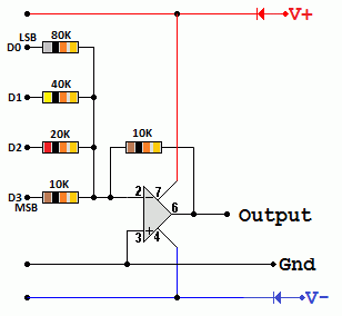
Summing Amplifier Digital to Analogue Converter

Summing Digital to Analogue Converter

In this diagram if the binary input is 0101, using the summing amplifier formula ...

Vout = -Rf ( V1 / R1 + V2 / R2 + V3 / R3 ... )

Vout = -10 ( 0 / 10 + 5 / 20 + 0 / 40 + 5 / 80 ) = 250 / 80 = -3.125 Volts

Resolution

Resolution is the size of the voltage steps as the digital data is incremented (add one) or decremented (subtract one).

0.625 Volts is the size of the smallest step. This is the resolution of the DAC.

Digital Ramp

If the DAC above is driven with a signal from a binary up counter increasing from 0 to 15, the output voltage will decrease in steps of 0.625 Volts.

This gives an output like this ...

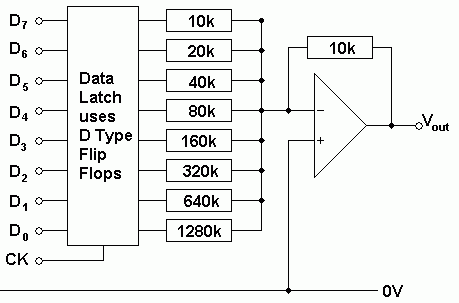
8 Bit Latch and Summing DAC

Here is a diagram showing an 8 bit DAC with a data latch.
Summing DAC Latch

On the rising edge of the clock pulse, the data is latched (stored in the latch).

The latch is needed if the input data is frequencly changing or not always available. When the input is valid, the rising edge of the clock causes the latch to store the data.

For example, this circuit might be connected to the data bus of a computer. Most of the time the bus is carrying data that is nothing to do with the DAC output. If the DAC is memory mapped, an address decoder would be used to trigger the clock in response to the latch's particular address.

Subject Name     Level     Topic Name     Question Heading     First Name Last Name Class ID     User ID    

fff
Home
<<<
ppw
Pg Up
<<
ppp
Up
<
|||

>|<
nnn
Down
>
nnw
Pg Down
>>
lll
End
>>>

Close
Escape
X

Q: qNum of last_q     Q ID: Question ID         Score: num correct/num attempts         Date Done    


Submit
Enter


Question Text

image url


Help Link

Add     Delete     Clone     Edit     Hardness

Help Text
Debug


Contact, Copyright, Cookies and Legalities: C Neil Bauers - reviseOmatic V4 - © 2016/17

Hosted at linode.com - London


Please report website problems to Neil