
RANDOM PAGE
SITE SEARCH
LOG
IN
SIGN UP
HELP
To gain access to revision questions, please sign up and log in.
Everyone
aSimplifying Complex Systems
Complex electronic systems can be difficult to design, understand and test.
It is a good idea to modularise systems so each module is relatively simple.
This makes it easier for designers and fabricators to work in teams. Each team member can work on their own module. Many very useful modules are available pre-designed and built.

Working from the top down you have a 555 timer, an LM380 Audio Amplifier, an eight bit Darlington Driver and two Programmable Integrated Circuits (PICs).
bMicrochips
One of these modules might contain several subsystems. For example, a 555 timer contains six subsystems, all of which are on the AQA specification.
c555 Timer Module - Subsystems
- a voltage divider
- two comparators
- a flip flop
- an output driver circuit
- a bipolar transistor used as a switch
dMore Subsystems and Modules
As well as single chips, it is possible to get complete modules, sometimes with input and output devices. Examples include ...
- Ultrasonic Range Finder
- Digital FM UHF Transmitter
- Digital FM UHF Receiver
- Temperature Sensor (more accurate and easier to use than a thermistor)
- Humidity Sensor
- GPS Satellite Receiver
- Infrared Receiver (as used in remote controls)
- Many many more ...
eSubsystems and System Diagrams
To describe the subsystems or modules in a complex system, block diagrams are used. Most systems consist of the following elements.
fSignals
- A current, voltage, sound, radio wave or light beam representing meaningful information.
gTransducers
- All transducers convert energy from one type into another.
- Input transducers or sensors are used for measuring, sensing or recording from the environment.
- Output actuators produce mechanical movement. Other output transducers might make sounds or use lights or displays to give information.
hInput Sensors or Transducers
The input typically comes from a measurement sensor or transducer. Examples include ...
- Switches (many types)
- Variable resistors
- Light measurement using a Light Dependent Resistor (LDR)
- Temperature measurement using a Temperature Dependent Resistor (TDR)
- Sound wave measurement using a microphone.
- Pressure, speed, position, acceleration, size, thickness, weight and many more ...
iProcess
The input signal is processed in some way. A decision might be made. The input signal might be amplified. The input signal could be converted into a new form ready for transmission to another system elsewhere.
- Compare two or more signals
- Amplify the input
- Convert an analogue signal to a digital data stream (A to D converter)
- Convert a digital data stream back to analogue (D to A converter)
- Switch a device on or off based on the input signal levels
- Count pulses
- Timing
- Measure the length of pulses
- Measure the time when pulses occur
- Decode patterns of pulses
- Logic Decision Making
- Memory
jOutput Transducers
Output transducers are used to produce a visible or audible signal. Alternatively actuators convert the electrical output into movement used to control machinery.
- Motor
- Servo
- Lamps, LEDs, LCD displays
- Loudspeaker
- Relay
- Solenoid
- More
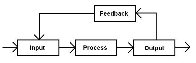
kInformation Flows
The flow of information through a system is shown with labelled arrows. Don't forget the labels. Don't forget the arrow heads to show the direction. The information is carried by currents, voltages, sound waves, ultra-sound, radio waves, pulses of light or by some other method. There are lots of ways to get information from one place to another.
lFeedback - A2 Topic
Open Loop control systems do not use feedback and the output is not measured.
Closed Loop control systems measure the output. This measurement is fed back to the input where it is used to correct errors in the output.
Negative Feedback - Usually a good thing. The feedback is used to correct errors in the output.
Positive Feedback - Useful in the Schmitt trigger, bistable, monostable, astable and other oscillator circuits. Otherwise it can be a bad thing. The feedback makes the error in the output worse. If a microphone picks up the signal from loudspeakers there is often a loud howling noise. This is an example of unwanted positive feedback. Carefully controlled positive feedback in radio frequency amplifiers (regeneration) increases the gain and selectivity of the circuit without unwanted oscillations.
Closed Loop Example - Expensive cars have cruise control.
- The input is an electrical signal that represents the speed the driver wants.
- The feedback is the actual speed of the vehicle (the speed sensor produces a voltage proportional to the speed).
- The process calculates the difference between the required and actual speeds and generates a control signal that is used to control the engine throttle actuator.
- The output is managed by an actuator used to increase or decrease the fuel flow to the engine.
mAnalysing a System
To Analyse a system, break it down into smaller parts (sub-systems), each of which is simpler and easier to understand than the whole system.
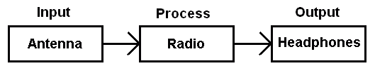
For example, you might have a complete system such as a radio. First locate the input, the process and the output.
- INPUT: Antenna
- PROCESS: Radio
- OUTPUT: Headphones (or loudspeaker)
Here is the simplified block diagram of a radio showing sub-systems without too much detail.
This simple diagram can be expanded to show extra detail. Often a module contains several subsystems. These can be shown on the more detailed diagram.
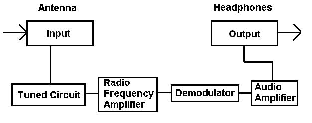
Each subsystem can be analysed in further detail. The highest level of detail consists of Layout and Circuit Diagrams - These show all the details with every component shown.
nDesign
Design is not easy for beginners. For starters, complete beginners will not know what is possible and will not be familiar with the basic building blocks used in electronics.
Some serious learning of the basics helps a lot.
To design a system ...
- identify the Input, the Process and the Output
- decide what input sensor/s to use
- decide what output devices to use
- decide how to process the input signals to generate the correct output
- produce a detailed specification See Below.
oExample Specification Including Testing
- If it's too hot, sound the alarm.
- Work on 12 to 15 Volts. (Test with a volt meter)
- If the temperature is above 35 C, sound the alarm (Test with a thermometer)
- The alarm will be a loud tone on a frequency between 3500 and 4000 Hz (Test with an oscilloscope)
- The alarm will be louder than 80 dB. (Test with a sound level meter)
- The 35 C temperature will still be correct at any power supply voltage between 12 and 15 Volts.
Real Life: You get paid for your work if your circuit meets the specification and passes all the tests.
A Level Work: AQA gives you a good project mark if your circuit meets the specification and passes all the tests.
Important: The specification contains actual electronics measurements and values that are possible to test. Without these, you have not got a specification.
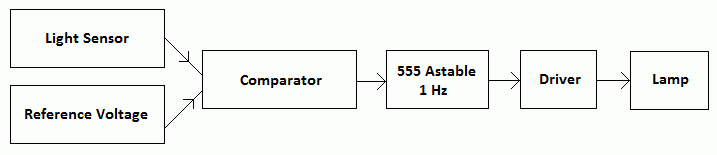
pA Temperature and Light Sensor
An electronic system sounds a warning signal when the temperature and the light intensity both fall below set levels.
For example this could warn a horticulturist about night-time frosts.
The system contains ...
- an audible warning device
- a light sensor
- a temperature sensor
- a comparator
- a logic gate
- a driver
The task is to label the diagram.
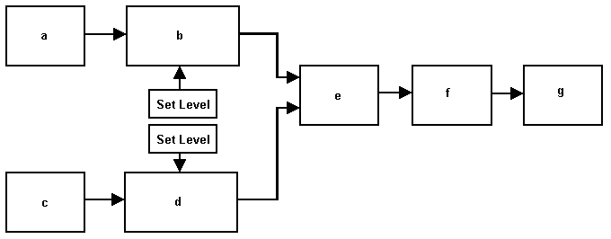
qInputs
- The temperature sensor - use a thermistor - box a
- The light sensor - use an LDR - box c
rReference Levels
These are set so the system responds to the correct light level and temperature.
sProcess 1
This control system uses two comparators for the processing. Comparators are based on Operational Amplifiers.
- Temperature comparator - box b
- Light level comparator - box d
tProcess 2
If both comparators are active (too cold) and (night time) these signals are processed with an AND Logic Gate - box e
Depending on the sensor outputs and driver input, different gates might be needed to get the right behaviour.
More about Logic Gates
uTransducer Driver
The AND Gate output is not sufficient to drive the alarm. A driver is needed - box f
- A MOSFET could be used.
- A bipolar transistor could be used.
vOutput
The audible warning device - box g.
wAnother Example
In this circuit ...
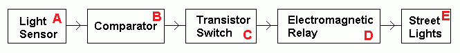
- A is the Input Device.
Use an LDR or a Phototransistor.
- B is the Process or Processor.
This converts the light level analogue input into a digital on/off output.
Use an Op Amp.
- C is a Driver for the Relay.
Use a MOSFET or Transistor Switch.
- D is a Driver for the Street Lights.
Use an Electromagnetic Relay.
A small electromagnet coil current operates the switch which carries a much larger output current.
- E is the Output.
One or more Light Bulbs.
xA More Complex Buoy Flasher Example
Here is a fairly complex system. It breaks down into much simpler subsystems.
- This is a decoupling capacitor.
- This is a Voltage Divider providing a fixed or set level.
- This is a second Voltage Divider providing a voltage that increases if the light level increases.
- This is a comparator subsystem. If the ANALOGUE input light level goes below the set level, the DIGITAL output goes high.
- This is an Astable designed to flash the lamp at regular intervals but only if it's dark. If the output from "O" is high, the astable oscillates.
- Q this is a transistor switch used as a transducer driver. The output transducer is the lamp. It converts the electrical signal into light.
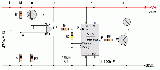
Decoupling
- C3 is a decoupling capacitor. It prevents momentary changes in power supply voltage that might upset the comparator.
Voltage Dividers
- R1 and R2 form a voltage divider. These values determine the light level at which the comparator operates.
- R3 and the LDR form another voltage divider. This one is sensitive to light.
- When it gets darker, the resistance of the LDR increases,
- When it gets darker, the voltage at B decreases.
The Comparator
- When the voltage at B is less than the voltage at A, the comparator output goes high.
- When the comparator output is high, the astable is activated.
The Astable
- C1 charges through R4 and R5 until the threshold voltage reaches 2/3 of 9 Volts = 6 Volts.
- Then the 555 output goes low.
- The discharge transistor turns on.
- C1 discharges through R5 until the trigger voltage drops below 1/3 of 9 Volts = 3 Volts.
- Then 555 output goes high.
- The discharge transistor turns off.
- C1 charges through R4 and R5 until the threshold voltage reaches 2/3 of 9 Volts = 6 Volts.
- These steps repeat once per second until it gets light and the comparator output goes low.
The Driver Transistor
- The 555 timer high output is used to turn on a driver transistor wired up as a switch.
- R6 limits the base current to a safe level.
- The transistor amplifies the base current and turns on the transistor switch.
- When the switch is on, the collector voltage drops close to zero and the lamp comes on.
Complete Circuit Behaviour
- The whole circuit flashes the lamp once per second when it's dark.
reviseOmatic V3
Contacts, ©, Cookies, Data Protection and Disclaimers
Hosted at linode.com, London