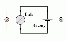
Connect the voltmeter in parallel with the component who's potential difference you want to measure.
The circuit below shows the battery voltage being measured and also the voltage across the bulb. (the same in this case)


Voltage EMF PD |
|
To gain access to revision questions, please sign up and log in.
a
Ideal voltmeters ...
Real voltmeters come close to the ideal but are never perfect.
c |
Connect the voltmeter in parallel with the component who's potential difference you want to measure. The circuit below shows the battery voltage being measured and also the voltage across the bulb. (the same in this case)
|
This identifies the positive (+) and the negative (-) ends of components. Getting the polarity right can be very important. Electrolytic Capacitors and many semiconductors are destroyed if the polarity is wrong. The failure can be explosive.
e
 |
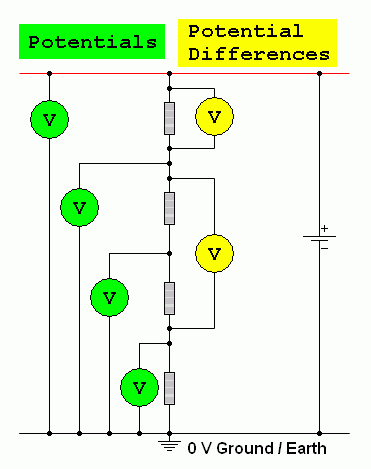
fPotentialThis is voltage measured relative to the the zero Volt ground potential. gPotential DifferenceThis is the difference between two potentials. It is measured across components by connecting a Volt meter in parallel with the device to be measured. hVoltageThis is just a slack usage of language. You should specify EMF, Potential or Potential Difference. As these concepts are all very similar, voltage is often used instead. iThe Volt
|
For the Falstad Circuit Simulation, CTRL+Click Voltage Divider Simulation
In options, check European Resistors and uncheck Conventional Current.
Click the switch to turn the circuit on or off. Watch the voltages change.
Alternatively view Voltage_PD_EMF.txt.
Save or copy the text on the web page. Import the saved or copied text into the Falstad simulator.
Here is the new HTML5 Simulator Site.

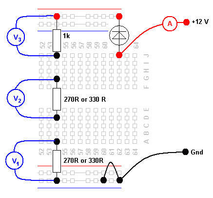
Build this circuit and measure V1, V2 and V3. Also measure the current flowing.
reviseOmatic V3 Contacts, ©, Cookies, Data Protection and Disclaimers Hosted at linode.com, London