Inductors |
|
To gain access to revision questions, please sign up and log in.
a

It takes a lot of energy to build up the magnetic field surrounding the inductor. It takes yet more energy to change the magnetic field. If you try to stop or change the current in the inductor suddenly, enormous voltages are produced (possibly destroying neighbouring components). This is called back EMF.
A good but slightly painful way to demonstrate inductance is to wire up this circuit. It takes about 60 volts to light a neon bulb. Using a 1.5 volt battery or a 5 volt power supply, every time the switch is opened, the neon flashes. This demonstrates the large back EMF when the current in the inductor changes suddenly.
Note: This may not be safe or even legal! The neon bulb can be replaced by a brave student volunteer who will suffer a small electric shock each time the switch is opened. An entire class can be electrocuted if all the students hold hands and the ones at the end of the circle hold the wires where the neon bulb goes.
Electric Fence: A circuit like this uses a timer to operate the switch to generate high voltage pulses about once per second. These are fed into an the electric fence to keep farm animals in their field.
A similar circuit generates pulses to create sparks in petrol (gasoline) engines. Up to 6000 accurately timed pulses are needed per second.
For the Falstad Circuit Simulation, CTRL+Click Inductor Back EMF Simulation
In options, check European Resistors and uncheck Conventional Current.
Click both switchs on and off in all four possible ways.
Alternatively view Inductor.txt.
Save or copy the text on the web page. Import the saved or copied text into the Falstad simulator.
Here is the new HTML5 Simulator Site.
Using a flywheel analogy, the current is the wheel rotation and the voltage is the force needed to get the wheel moving. A large force (voltage) is needed to accelerate the wheel. After a time delay, the wheel speeds up (current). Once the wheel is spinning, the driving force (voltage) can be removed and the flywheel will keep spinning (for a long time). The voltage leads the current.
If a spanner is thrown into the flywheel, the wheel will stop suddenly, destroying the spanner, wheel bearings, and the wheel. (A big flywheel would take out the entire building!). This is just like back EMF.
Adding an iron core to an inductor greatly increases the amount of energy that can be stored magnetically so the inductance also increases.
Solid iron is not an ideal material for a core because eddy currents are induced in the iron wasting energy in the form of heat. Thin slices of iron insulated from each other (a laminated soft iron core) prevent these currents and greatly improve the efficiency of the inductor. "Soft" means easily magnetised and de-magnetised.
Another useful core material is ferrite. This is iron dust glued and moulded into a solid shape. The glue insulates the iron particles from each other preventing eddy currents.
eXL = 2 p f L
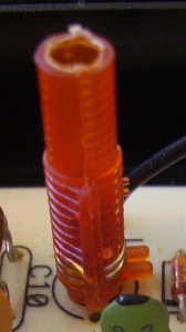
Pre-set variable inductors can be made by winding a coil and placing a ferrite core down the middle that can be screwed in or out. Threaded plastic coil formers with a screw thread and moulded ferrite slugs are available. Once adjusted, the slug can be secured with a drop of molten wax or nail varnish.
Screened Inductor used for an Intermediate Frequency Tuned Circuit
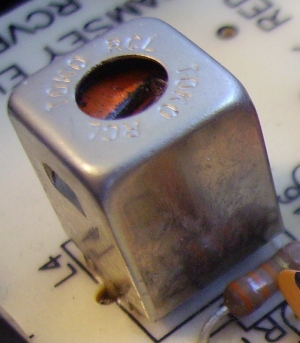
This is tuned by moving the Ferrite Slug.

These pass DC and low frequencies but block high radio frequencies.
hTwo inductors near each other can transfer energy magnetically. This is used in power system transformers to step voltages up or down. It's also used in radio circuits for coupling Radio Frequency energy from one subsystem to another.
i
reviseOmatic V3 Contacts, ©, Cookies, Data Protection and Disclaimers Hosted at linode.com, London