Site Logo Home
 
rOm
Quest
Glossary
 
Random
Page
Search
Site
Lush
Sim
Class
Subject
Images
 
Help
FAQ
Sign
Up
Log
In
GCSE     Transducer     Battery     Bulb     Buzzer     >Driver<     Loudspeaker     Microphone     Motor     Neon     Piezoelectric Sounder     Servo     Seven Segment     Solenoid    

Transducer Driver


Site for Eduqas/WJEC - Go to the AQA site.

  GCSE    Transducers  0 of 12    Question 252    Components 
Score 0/0 
Not attempted  
Last Answer  
Deadline not set1 of 12    Question 1035    Robot Inputs 
Score 0/0 
Not attempted  
Last Answer  
Deadline not set2 of 12    Question 1032    Robot Outputs 
Score 0/0 
Not attempted  
Last Answer  
Deadline not set3 of 12    Question 1033    Robot Outputs 
Score 0/0 
Not attempted  
Last Answer  
Deadline not set4 of 12    Question 1034    Robot Outputs 
Score 0/0 
Not attempted  
Last Answer  
Deadline not set5 of 12    Question 1023    Robotic Vision 
Score 0/0 
Not attempted  
Last Answer  
Deadline not set6 of 12    Question 1024    Robotic Vision 
Score 0/0 
Not attempted  
Last Answer  
Deadline not set7 of 12    Question 1026    Robotic Vision 
Score 0/0 
Not attempted  
Last Answer  
Deadline not set8 of 12    Question 1086    Robots and Machines 
Score 0/0 
Not attempted  
Last Answer  
Deadline not set9 of 12    Question 1501    Transducer Buzzer 
Score 0/0 
Not attempted  
Last Answer  
Deadline not set10 of 12    Question 266    Transducers 
Score 0/0 
Not attempted  
Last Answer  
Deadline not set11 of 12    Question 279    Transducers 
Score 0/0 
Not attempted  
Last Answer  
Deadline not set12 of 12    Question 283    Transducers 
Score 0/0 
Not attempted  
Last Answer  
Deadline not set  Questions 0 to 12   -->  View All  

Small signals from processing devices often need to be boosted by a DRIVER before connection to an output transducer.

For example, street lights might be controlled by a small light sensor connected to a 40106 chip. This chip has a maximum output current of around 10mA at 5 Volts DC. The street lamps probably run on 230 Volts AC with a current of 400mA per light.

INPUT -  The input sensor is the LDR.

PROCESS -  The Schmitt NOT gate is the processor.

DRIVER -  The transistor switch is a driver. The relay could also classed as a driver.

OUTPUT -  In this case, the lamps are the output transducers. They convert electrical energy into light.

Transducer Driver

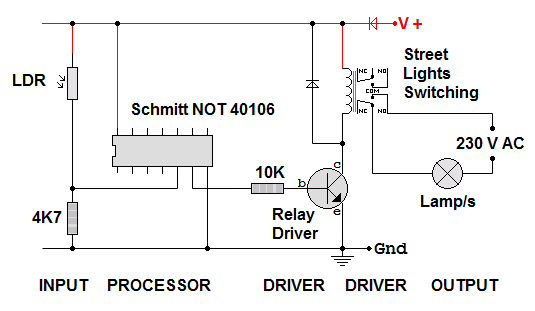
A light sensing voltage divider made from the LDR and 4K7 resistor is connected to the Schmitt NOT gate. On its own this can't drive the street lights. It can't even drive the relay.

The NPN transistor acts as a switch, turning the relay on or off.

The relay is capable of switching the 230 V AC current for the street lights.


Subject Name     Level     Topic Name     Question Heading     First Name Last Name Class ID     User ID    

fff
Home
<<<
ppw
Pg Up
<<
ppp
Up
<
|||

>|<
nnn
Down
>
nnw
Pg Down
>>
lll
End
>>>

Close
Escape
X

Q: qNum of last_q     Q ID: Question ID         Score: num correct/num attempts         Date Done    


Submit
Enter


Question Text

image url


Help Link

Add     Delete     Clone     Edit     Hardness

Help Text
Debug


Contact, Copyright, Cookies and Legalities: C Neil Bauers - reviseOmatic V4 - © 2016/17

Hosted at linode.com - London


Please report website problems to Neil