
NOT Gate Astable |
|
To gain access to revision questions, please sign up and log in.
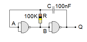
This circuit can be used to build a clock to drive sequential logic circuits. However the frequency changes when the power supply voltage changes. A 555 Astable has better frequency stability. A quartz Crystal Oscillator gives the best stability. The upper frequency limit is determined by the chip speed. The NOT gate would be the winner here. For low frequencies, you can use an Op Amp as a Relaxation Oscillator.
Period = 2RC
Frequency = 1 / Period
Frequency = 1 / 2RC
The circuit is astable. That means it can not permanently settle in an on or off state. It has ZERO stable states. Whichever state it is in, the capacitor will charge or discharge eventually causing it to switch to the other state. Once in the other state, it is still unstable and the circuit oscillates.
Try the 4069UB unbuffered hex NOT gate from the 4000 CMOS family of chips.

For the Falstad Circuit Simulation, CTRL+Click Astable Using Not Gates
In options, check European Resistors and uncheck Conventional Current.
Turn on the switch to start the astable.
Alternatively view NOT_Gate_Astable.txt.
Save or copy the text on the web page. Import the saved or copied text into the Falstad simulator.
Here is the new HTML5 Simulator Site.
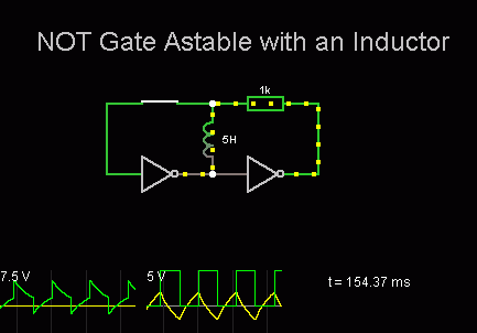
Period = 2L / R
Frequency = 1 / Period
Frequency = R / 2L

For the Falstad Circuit Simulation, CTRL+Click Astable Using Not Gates and an Inductor
In options, check European Resistors and uncheck Conventional Current.
Turn on the switch to start the astable.
Alternatively view NOT_Gate_Inductor_Astable.txt.
Save or copy the text on the web page. Import the saved or copied text into the Falstad simulator.
Here is the new HTML5 Simulator Site.
reviseOmatic V3 Contacts, ©, Cookies, Data Protection and Disclaimers Hosted at linode.com, London