
Quadrature Amplitude Modulation |
|
To gain access to revision questions, please sign up and log in.
Analogue AM Sample. The quality is quite nasty. There is a high pitched heterodyne whistle and periods of signal fading causing serious distortion.
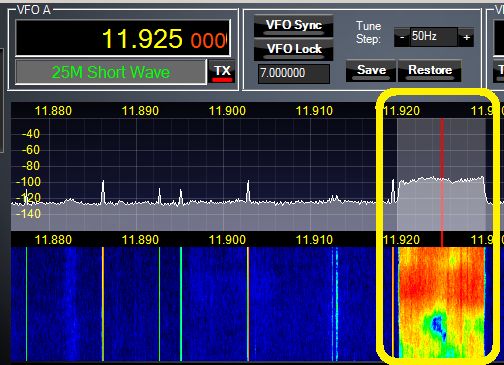
DRM Digital Radio Sample. This is quite a large download and might not stream well. The image shows a spectrum plot of the short wave HF DRM, Digital Radio Mondiale, transmission.

Most digital transmissions use QAM, quadrature amplitude modulation with many carriers. Using many carriers is a type of frequency division multiplexing.
In the image above, you can see some carriers (vertical spikes / lines). The yellow highlighted area contains about 84 carriers, all modulated as explained below. You can also see selective fading where certain frequencies are much weaker than others. These are the green and blue areas. DRM can work much better than AM under these conditions.
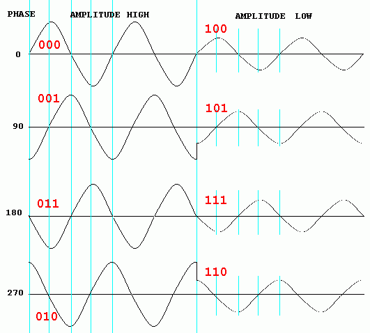
This diagram shows a QAM8 signal at four phase angles with 100% amplitude and the same four phase angles at 50% amplitude. This can be used to encode three bits per symbol where a symbol is the smallest unit of transmission. The bits are in Gray code order. More complex versions of QAM exist but are hard to visualise.
Receivers or decoders can display QAM like this.
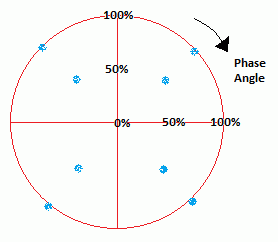
The plot above shows three bit symbols (blue dots) at 50% and at 100% amplitude and at all four phase angles.
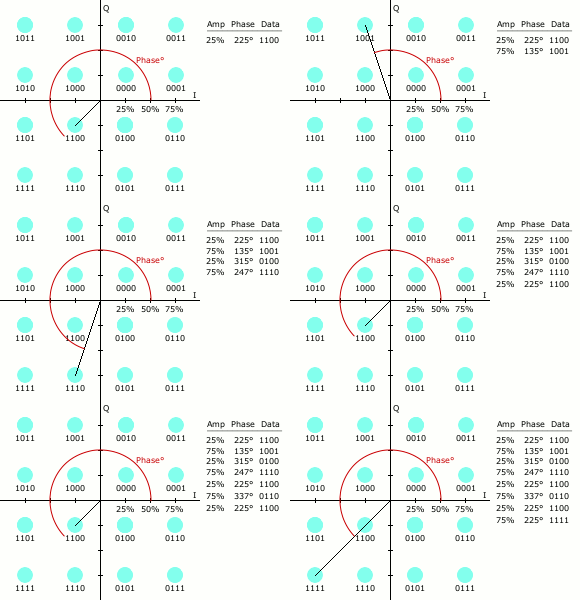
This nice little animation shows the phase angle and amplitude changing to represent four bit symbols.
Here is a plot for a DRM transmission on 11.925 MHz. Notice how noise displaces the dots from their theoretical ideal positions.
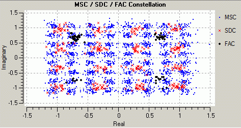
This QAM transmission uses the same ideas as described above but a more complex modulation scheme is being used.
reviseOmatic V3 Contacts, ©, Cookies, Data Protection and Disclaimers Hosted at linode.com, London