Picaxe 7 Segment Display |
|
To gain access to revision questions, please sign up and log in.
; ===== Count from 0 to 9 (INCOMPLETE) =====

START:
        MOVW    0X08        ; 0
        CALL    SEG
        MOVW    0X3E        ; 1
        CALL    SEG
        MOVW    0X11        ; 2
        CALL    SEG

        JMP     START

; ======= SUBROUTINE ========
SEG:
        MOVWR   PORTB
        CALL    WAIT100MS
        CALL    WAIT100MS
        CALL    WAIT100MS
        RET
; ======= END SUBROUTINE ====
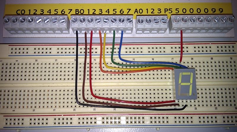
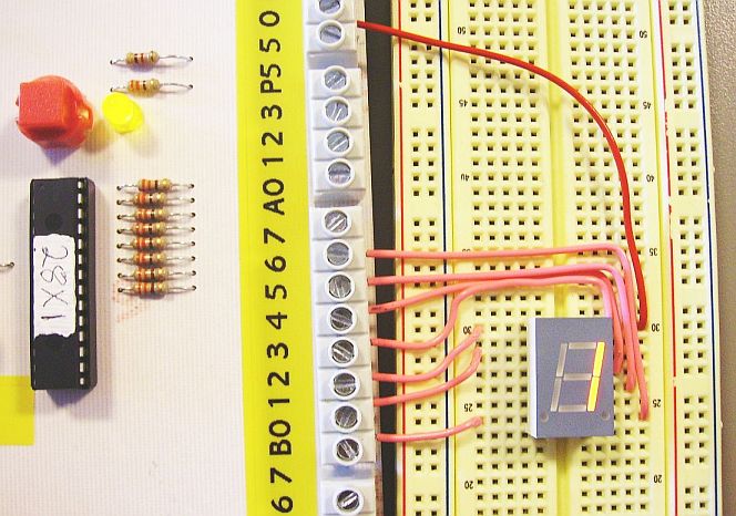
There are two common Seven Segment Display pinouts. Use one of the next two diagrams as a guide.
If you are using the ENSFC board, you don't need current limiting resistors because these are built into the circuit board.

CTRL+Click here to run the simulator.
; ===== This code has been tested =====
main:
    movw    0x7D            ; Display a Zero
    movwr   PORTB
    call    wait100ms       ; Delay 300mS
    call    wait100ms
    call    wait100ms
    movw    0x05            ; Display a One
    movwr   PORTB
    call    wait100ms       ; Delay 300mS
    call    wait100ms
    call    wait100ms
    movw    0x5B            ; Display a Two
    movwr   PORTB
    call    wait100ms
    call    wait100ms
    call    wait100ms

                            ; FINISH THIS
    jmp main

wait100ms:
    NOP
    NOP
    RET
reviseOmatic V3 Contacts, ©, Cookies, Data Protection and Disclaimers Hosted at linode.com, London