Infrared Data Link |
|
To gain access to revision questions, please sign up and log in.
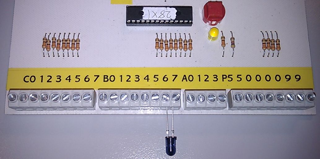
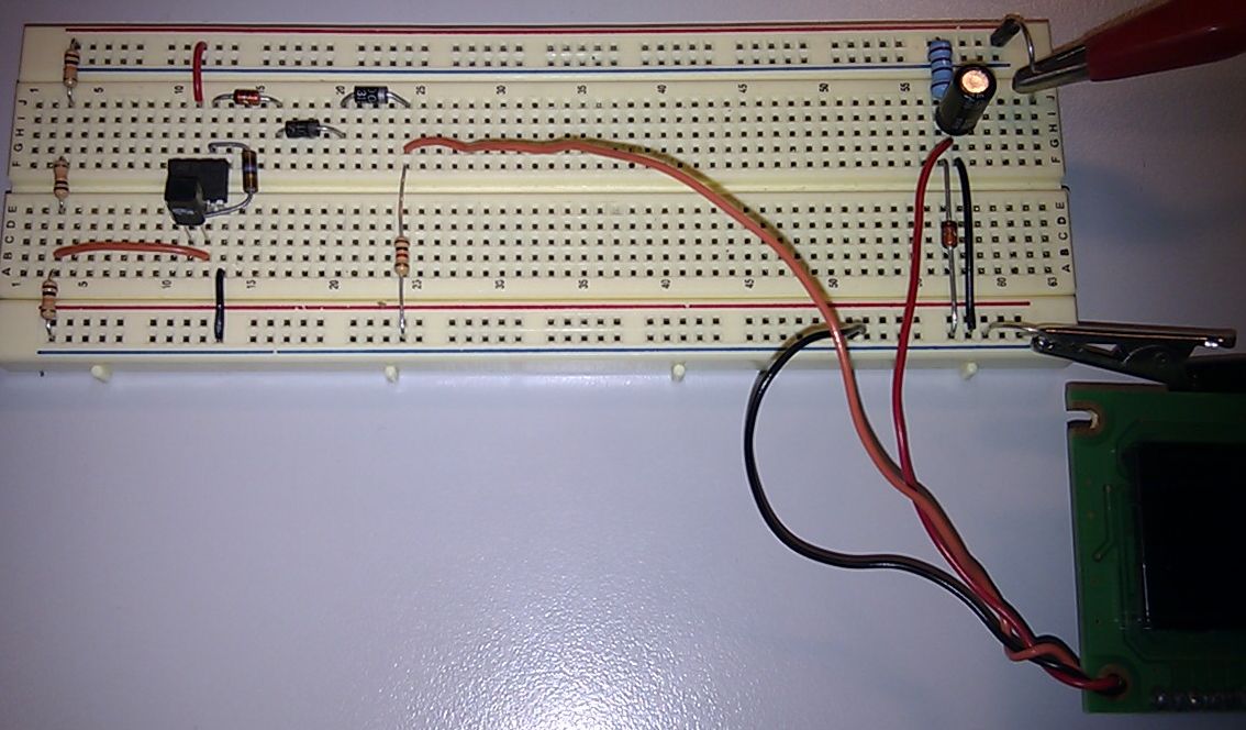
Two pull down switches are used as Picaxe data inputs allowing up to four text messages to be sent.
The sample code below does not use these.
The 1K resistors give a safe hardware interface.
If the Picaxe code is wrong and C.0 or C.1 are accidentally configured as outputs, the current is limited and there will be no damage.
The Infrared LED is wired to B.7. The other leg should go to ground but B.6 held LOW does the trick too.
There is no current limiting resistor as these are built into our Picaxe boards. 330R should be used if necessary.
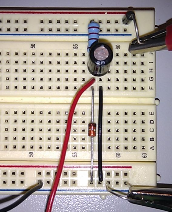
The two zener diodes ensure correct voltages reach the OLED or LCD display.
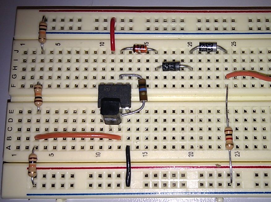
The 5.1V Zener diode to ensures a 5 Volt supply for the OLED or LCD display.
; ================================
; ===== Infrared Transmitter =====
; ================================

    SETFREQ M4
    CALL    WAIT1000MS
    LOW     6
START:
    CALL    blank
    CALL    WAIT1000MS
    CALL    TESTTEXT
    CALL    WAIT1000MS
    JMP     START

; ======================================
; A subroutine to blank both lines.
; ======================================
blank:
    serout 7, N2400, (254, 128)   ' Blank First Line
    serout 7, N2400, ("                ")
    serout 7, N2400, (254, 192)   ' Blank Second Line
    serout 7, N2400, ("                ")
    ret
; ======================================

; ======================================
; A subroutine to show some test text.
; ======================================
TESTTEXT:
    serout 7, N2400, (254, 128)   ' First Line
    serout 7, N2400, ("0123456789ABCDEF")
    serout 7, N2400, (254, 192)   ' Second Line
    serout 7, N2400, ("FEDCBA9876543210")
    ret
; ======================================
reviseOmatic V3 Contacts, ©, Cookies, Data Protection and Disclaimers Hosted at linode.com, London