PWM Motor |
|
To gain access to revision questions, please sign up and log in.
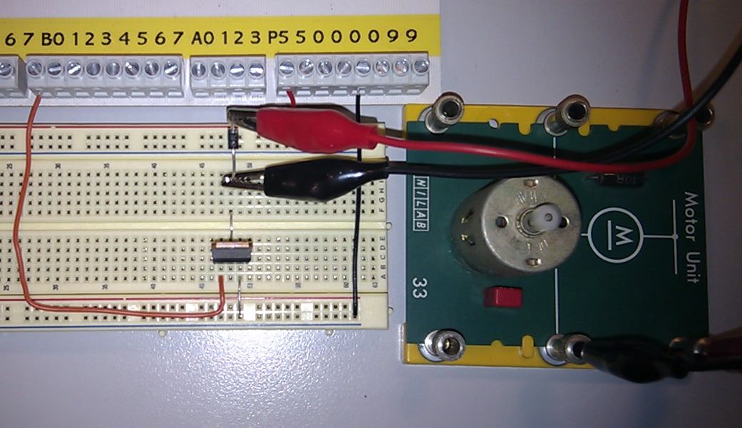
This image shows the Picaxe chip generating pulses of decreasing width.
This has the effect of slowing the conncted motor from 100% speed down to zero%.
Here is a MOSFET motor driver.
The Circuit Diagram
And Finally the Code
    SYMBOL  COUNTER1 = B0
    SYMBOL  COUNTER2 = B1

INIT:
    COUNTER1 = 50    ; CONTROL THE PULSE HIGH TIME
    COUNTER2 =  0    ; CONTROL THE PULSE LOW TIME

START:
    DEC     COUNTER1 ; REDUCE THE HIGH PULSE WIDTH
    JPZ     INIT     ; NOTICE WHEN COUNTER1 HAS REACHED ZERO

    MOVW    0X01     ; SET OUTPUT HIGH
    MOVWR   PORTB    ; MOTOR IS CONNECTED TO PORTB
    MOVRW   COUNTER1 ; USED TO TIME THE HIGH PULSE
LOOP1:
    JPZ     NEXTBIT  ; IF ZERO, DO THE NEXT BIT
    SUBW    1        ; COUNT DOWN TOWARDS ZERO
    JMP     LOOP1    ; JUMP BACK TO CARRY ON COUNTING DOWN

NEXTBIT:
    INC     COUNTER2 ; INCREASE THE LOW PULSE WIDTH

    MOVW    0X00     ; SET MOTOR OUTPUT LOW
    MOVWR   PORTB    ; MOTOR IS CONNECTED TO PORTB
    MOVRW   COUNTER2 ; USED TO TIME THE LOW PULSE
LOOP2:
    JPZ     START    ; IF ZERO, JUMP TO THE START
    SUBW    1        ; COUNT DOWN TOWARDS ZERO
    JMP     LOOP2    ; JUMP BACK TO CARRY ON COUNTING DOWN
reviseOmatic V3 Contacts, ©, Cookies, Data Protection and Disclaimers Hosted at linode.com, London