
Picaxe LDR and LCD |
|
To gain access to revision questions, please sign up and log in.
This is a tricky concept for a programming beginner.
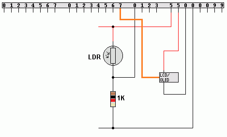
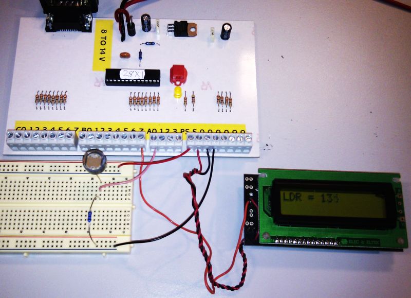
Build this circuit and copy and paste the code below.


    setfreq m4        ; 4MHz Internal Clock

    call    blank
start:
    call    readadc0  ; readadc0 is NOT an AQA instruction
                      ; Read the ADC and store the value into B0.

    DEBUG             ; Comment this out if everything works OK

    call    displayb0

    jmp     start

; ==========================================
; ===== These are NOT AQA instructions =====
; ==========================================
; bintoascii converts a number like 135 into
; "1", "3", "5". These ASCII codes can be
; copied to the LCD display.
; ==========================================
displayb0:
    bintoascii b0,b1,b2,b3
    serout 7, N2400, (254, 128)   ' Blank First Line
    serout 7, N2400, ("LDR = ",b1,b2,b3,"     ")
    ret
; ==========================================
; A subroutine to blank both LCD lines.
; ==========================================
blank:
    serout 7, N2400, (254, 128)   ' Blank First Line
    serout 7, N2400, ("                ")
    serout 7, N2400, (254, 192)   ' Blank Second Line
    serout 7, N2400, ("                ")
    ret
; ==========================================
This is not an accurate light meter but it demonstrates the principle.
This has only two "active devices" so, as it stands, it is not suitable for an A2 project.
Making an accurate light meter might be an ideal project.
reviseOmatic V3 Contacts, ©, Cookies, Data Protection and Disclaimers Hosted at linode.com, London