RANDOM PAGE
SITE SEARCH
LOG
IN
SIGN UP
HELP
To gain access to revision questions, please sign up and log in.
Non-Exam Extras
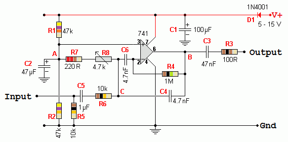
This tunable filter produces quite a nice sound effect by emphasising a range of frequencies that can be adjusted with R8.
With the potentiometer R8 at one extreme, the output peaks at about 500 Hz. At the other extreme, it's about 1000 Hz.

This circuit is based on a similar one from this site.
- D1 is a diode. This is used to protect against accidental connection of the power the wrong way round.
- C1 is a decoupling capacitor. Any power supply voltage fluctuations will be smoothed out by C1.
- R1 and R2 form a potential divider.
These resistors have equal values so the potential at A will be half the supply voltage.
This allows the 741 op amp to be used without a negative power supply.
- C2 is a decoupling capacitor.
It ensures that the potential at A is steady and any AC signals are coupled to the ground/earth power rail.
- C3 couples the signal output from the 741 op amp whilst blocking the DC potential at B.
- R3 protects the 741 from damage in the event that someone shorts the output to ground/earth.
The current will be limited to a level the 741 can withstand.
- R4 provides negative feedback to the inverting input of the 741. This limits the gain of the op amp.
- C4 provides additional negative feedback but only at higher frequencies. This reduces the gain of the op amp at high frequencies.
- C5 couples the input signal whilst blocking any DC potential at the input.
At point C the DC potential is about half the supply voltage.
This DC also needs to be blocked to prevent it reaching the input pin.
- R5 prevents a charge being present at the left end of C5.
Without this, there would be a loud bang whenever an input was connected.
This would be caused by the charging of C5.
- R6 acts together with R4 to control the maximum gain of the op amp.
The maximum gain will be no more than -R4/R6
- C6 blocks DC and low frequencies.
This means that the circuit will have a lower gain at lower frequencies.
C4 reduces gain at the higher frequencies.
This means that there will only be useful gain at middling frequencies.
This frequency range is called the pass band.
- R7 and R8 form a variable resistor.
R7 ensures that the minimum resistance is never less than 220Ω.
The maximum resistance will be 4.92k.
This variable resistance acts together with C4 and C6 to determine the frequency at which the gain is greatest.
By altering R8 the centre frequency of the pass-band can be altered.
reviseOmatic V3
Contacts, ©, Cookies, Data Protection and Disclaimers
Hosted at linode.com, London


