RANDOM PAGE
SITE SEARCH
LOG
IN
SIGN UP
HELP
To gain access to revision questions, please sign up and log in.
Non-Exam Extras
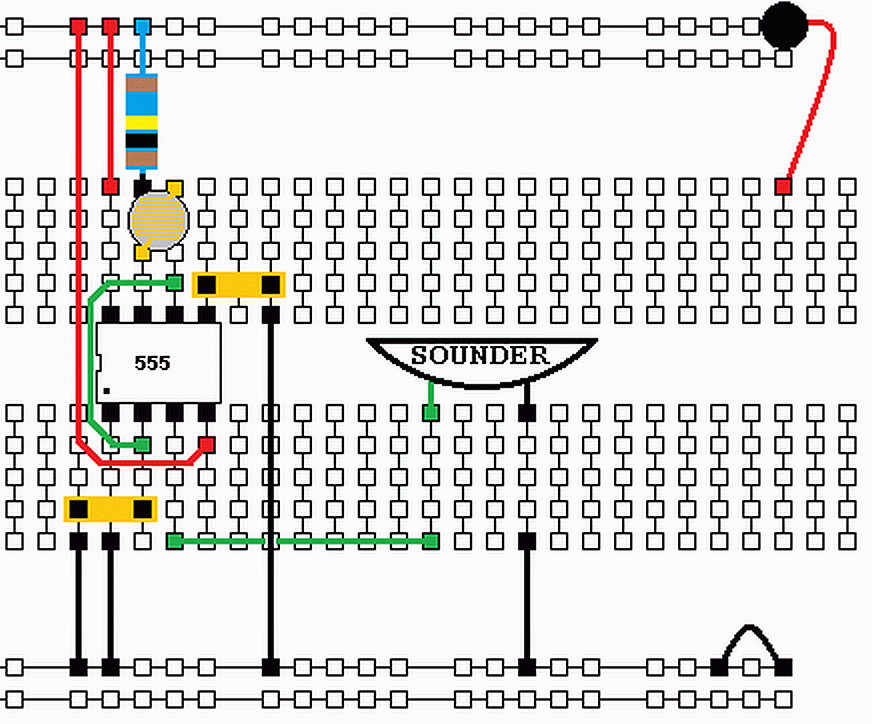
Build a Circuit to Buzz at a Variable Frequency. Here is a diagram of the layout.

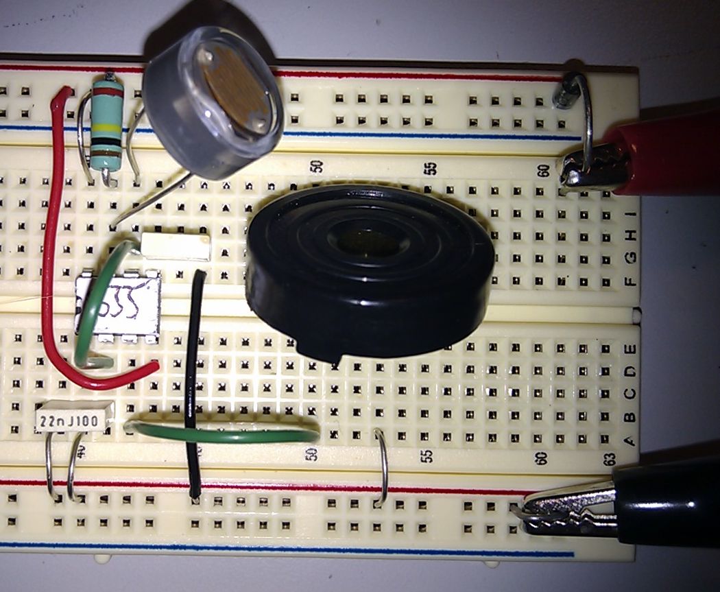
Here is a photo of the layout.

555 Timer Astable – Buzzer
- This circuit uses a CAPACITOR.
This is like an electronic bucket.
It’s repeatedly filled and emptied.
- The two RESISTORS control how quickly the CAPACITOR fills and empties.
- The light dependent resistor (LDR) makes it possible to play a tune by shading the light.
- The 555 Timer fills the CAPACITOR until it’s 2/3 full.
Then it empties it until it’s 1/3 full.
This repeats for ever and it controls the timing.
- The 555 also drives the SOUNDER.
- The DIODE passes current in one direction only.
If you wire up the power the wrong way round, this protects the circuit.
Websites for Electronics at East Norfolk Sixth Form College
http://reviseomatic.org/
Today’s Activity …
http://reviseomatic.org/help/x-more/Year%2010%20Astable%20Activity.php
Downloads: DOCX PDF
reviseOmatic V3
Contacts, ©, Cookies, Data Protection and Disclaimers
Hosted at linode.com, London


