 Home
Home
rOm
Quest
Glossary
Random
Page
Search
Site
Lush
Sim
Class
Subject
Images
Help
FAQ
Sign
Up
Log
In
WANTED: Individual or team to take over this project. I'm in my 70's and want to put my feet up. Contact details in footer.
Microcontrollers
Microcontrollers are simple but complete computers on a single silicon chip wafer. All the essential hardware is present, including the clock, memory, arithmetic and logic units, input and output subsystems and the firmware in ROM allowing the chip to be programmed. The chips contain both volatile and non-volatile memory. Many versions of the chips are available, balancing cost, speed, number of I/O connections and optional subsystems built into the chip.
-
PICAXE say they will suport the WJEC instructions in the same way that the AQA and OCR instructions are supported now.
-
This site recommends PICAXE for GCSE and AS Level. For A Level the "real thing" might be a better choice.
These pages use the "Bare Metal" tools from microchip.com - useful skills!
-
These tutorial pages are written for the PicKIT3 and MPLAB-X tools, native to the microchip.com family of microcontrollers..
-
Data Sheets and Guides: PIC16F88 Data Sheet PIC16F88 on Microchip.com Mid-Range MCU Family Reference Manual
-
Code samples on piclist.com: There is a mine of good information here.
-
A Good Tutorial at Elmer160: These tutorials are for the PIC16F84A. This is similar to the PIC16F88 but it lacks the A to D Converter.
-
UK Exams form WJEC/Eduqas: The PIC16F88 chip is mentioned in the WJEC/Eduqas A Level Draft Sample Assessment Material. It seems a reasonable choice, not too complex or expensive.
-
These Pages: Hopefully these tutorial pages, videos and examples will save students and teachers a lot of time learning assembly code programming.
-
The PICkit3 Programmer: The chip can be programmed easily with a PICkit3 industry standard low cost programmer.
-
MPLAB-X IDE: This is the integrated development environment. It's not too hard to learn. There are many advanced features not needed for beginners.
-
Example Code: The PIC16Fxxx family chips are quite similar so example code for one chip can often be used for another with minimal alteration.
-
Microcontrollers are also known as:
PIC - Programmable Integrated Circuit
SoC - System on a Chip
MCU - Microcontroller Unit
-
PIC16Fxxx chips have re-programmable flash memory. PIC16Cxxx chips can be programmed only once.

Chip Properties
Source: Page 161 of the data sheet above.
-
The chip typically runs on a 5 Volt supply, compatible with many families of logic chips. The absolute maximum is 7.5 V.
-
The maximum current for the whole chip is 200 mA.
-
The maximum current source or sink on any single I/O pin is 25 mA.
-
PORTA and PORTB are eight bits wide, capable of digital input and output.
-
The maximum current source or sink on PORTA or PORTB is 100 mA.
-
All the port pins can be configured as input or output except for RA5 which is input only.
-
Many port pins have alternative functions, if activated.
-
There is more detail in the data sheet.
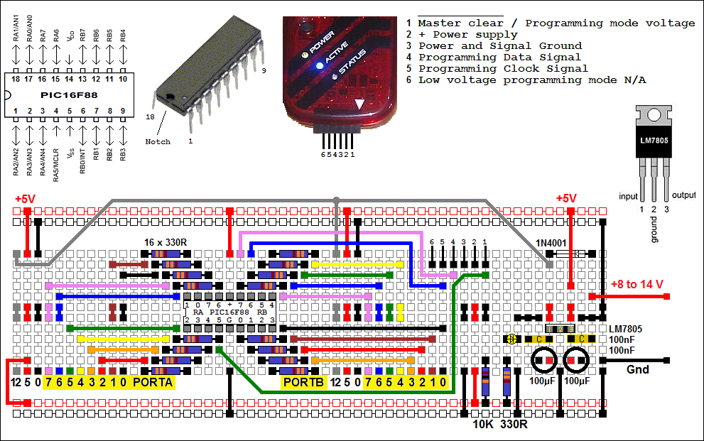
In Circuit Serial Programming (ICSP)
-
If pins 4, 12 and 13 (RA5, RB6 and RB7) are not needed for for your project, the chip can be re-programmed whilst wired up to the rest of your circuit.
-
If you don't need too many I/O lines, avoid using RA5, RB6 and RB7 for easier re-programming.
-
If you must use these pins for data input or output, the chip has to be unplugged from your circuit and plugged into a programmer board.
-
Clever use of switches, jumpers or other interfacing techniques could allow re-programming without moving the chip out of its circuit.
-
The chip programmer places +8 to 13V onto the MCLR pin for programming. If this pin is connected to other circuitry while programming the chip, there could be all sorts of problems.
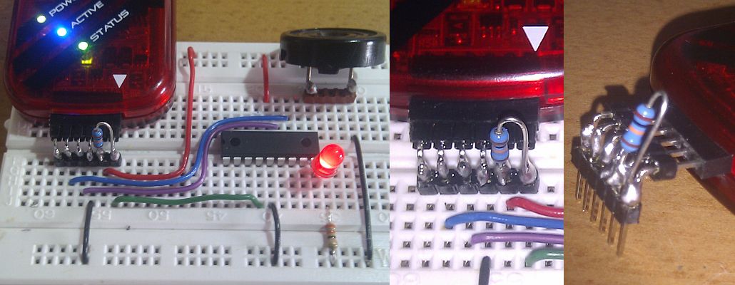
Shoestring Programmer - Powered from USB
-
Note the 10k pull-up. This can be wired to the connector if you don't need to use RA5 as a reset pin.
-
RA5 will normally be used as an I/O pn.
-
If you want to use RA5 as a reset pin, include the 10K on the shoestring board instead.
-
The LED and sounder are not part of the programmer.
-
They are present for the example programs coming next.
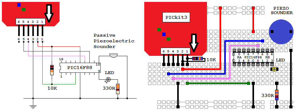
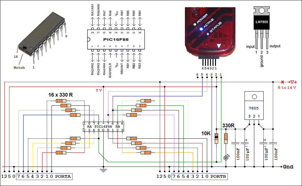
Circuit and Layout Diagram
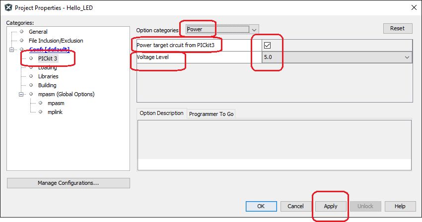
Power the Board From USB - 20mA Limit
In MPLAB-X, to power your board from the USB cable, use: File ↠ Project Properties ↠ Set it up like this.
Circuit Board and Layout - Not Normally Powered from USB
This is a home made board. The circuit diagram is below. The PICkit3 is plugged into the board ready for programming. Jumper leads connect to port pins.
Amazon ASIN: B00XBP8472 - Larger Raspberry Pi Proto Breadboard. There is an alternative smaller board - ASIN: B010VTVVHA.
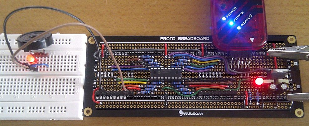
This board is designed to run on 8 to 14 Volts. The voltage regulator could be left out to run the board on 4.5 to 5 Volts. All the I/O pins have hard-wired current limiting resistors. Many students forget to include them when needed. Indeed I've already been saved by these resistors and I'm supposed to be the expert! The resistors have minimal effect if the pins are used as inputs.
A few times, I've accidentally reprogrammed my chip with LEDs connected to lines used by the programmer. It worked fine with apparently, no harm done. The programmer is on the safe side of the current limiting resistors.
The 7805 voltage regulator could do with a heatsink as it often runs rather hot. High current output devices should be powered separately.
Approximate Circuit Layout
This circuit was designed to run on an 8 to 14 Volt supply. If you don't need the higher voltages and there are no high current devices in your circuit, it can be powered via the PICkit3 from a USB port with a 20mA limit (a couple of LEDs).