WANTED: Individual or team to take over this project. I'm in my 70's and want to put my feet up. Contact details in footer.
PIC16F88 09 TMR0IF Interrupts |
|
Polling and interrupts are two approaches to event-handling such as an input change or a timer timing out.
Polling repeatedly checks the input or timer flag to see if it has changed. This is not very efficient because the processor is tied up doing these checks. It's a bit like a house without a doorbell. You have to check the front door every minute or so to see if anyone is there.
Interrupt processing is handed over to the chip hardware so the software can get on with other tasks without having to check flags or input changes. On every instruction cycle the hardware checks the inputs or flags and if there has been a change or a flag is set, the interrupt code is called. The hardware is still polling but it takes up no time from the running program.
If an interrupt takes place, the processor suspends whatever it's doing without delay. It handles the interrupt code and finally resumes the previous task. It's like the doorbell ringing. You answer the door. Collect the package (or whatever). Then go back to what you were doing earlier.
This is usually a better way of working.
This can be run in the Simulator or in real life.
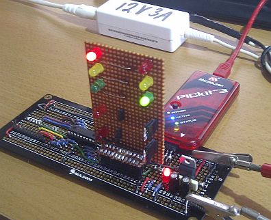
If eight LEDs are connected to PORTB, they will count in binary.
RB0 is a blur. RB2 is noticeably flickering. RB7 flashes at about 1 Hz.
The binary count is updated by the interrupt code every time TMR0 overflows.
;*******************************************************************************
; PIC16F88 Configuration Bit Settings
;*******************************************************************************
    #include "p16F88.inc"
; CONFIG1 - Internal oscillator - Want I/O - Everything else turned off
 __CONFIG _CONFIG1, _FOSC_INTOSCIO & _WDTE_OFF & _PWRTE_OFF & _MCLRE_OFF & _BOREN_OFF & _LVP_OFF & _CPD_OFF & _WRT_OFF & _CCPMX_RB0 & _CP_OFF
; CONFIG2 - Turn on both
 __CONFIG _CONFIG2, _FCMEN_ON & _IESO_ON

;*******************************************************************************
; Uninitialised Data - Reserve bytes here ...
;*******************************************************************************
	    UDATA
MyCount	    RES	    1	    ; reserves 1 byte - OK with simulator debug
; MyCount   EQU	    0	    ; FAILS with simulator debug

;*******************************************************************************
; RESET VECTOR
;*******************************************************************************
RES_VECT    CODE 0x0000     ; processor reset vector
    GOTO    CODE_INIT       ; beginning of program, initialise stuff

;*******************************************************************************
; INTERRUPT HANDLING
;*******************************************************************************
ISR	    CODE 0x0004	    ; The interrupt vector location is always 0x0004
    GOTO    ISR_HANDLER	    ; Jump to the Interrupt handling code

;*******************************************************************************
; MAIN PROGRAM
;*******************************************************************************
MAIN_PROG   CODE	    ; let linker place main program

CODE_INIT:		    ; INITIALISATION
    CALL    PORT_INIT	    ; Set up I/O Ports
    CALL    TIMER_INIT	    ; Set up Timer0
    GOTO    IDLE_LOOP	    ; Start the Idle Loop

;*******************************************************************************
; INTERRUPT SUBROUTINE
;     This ought to save and restore the context
;     It's not secessary in this simple example
;*******************************************************************************
ISR_HANDLER:
			    ; INCREMENT COUNTER - UPDATE PORTS
    INCF    MyCount, 1	    ; Increment MyCount - result into MyCount
    MOVF    MyCount, 0	    ; Copy MyCount to WREG
    MOVWF   PORTA	    ; Copy WREG to PORTA - Remember RA5 is input only
    MOVWF   PORTB	    ; Copy WREG to PORTB

			    ; RESTART TIMER
    BCF	    INTCON, TMR0IF  ; Remember to clear the INTCON TMR0IF flag
    MOVLW   d'250'	    ; TMR0 counts from 250 to 256 - short delay
    MOVWF   TMR0	    ; 250 copied into TMR0
    RETFIE		    ; Return from interrupt

;*******************************************************************************
; The Idle Loop
; MS Windows has an "idle process" which waits for the user to do something.
;*******************************************************************************
IDLE_LOOP:
    NOP
    NOP			    ; NOPs make code execution visible
    NOP
    NOP
    GOTO    IDLE_LOOP

;*******************************************************************************
; INITIALISE PORTS
;*******************************************************************************
PORT_INIT:
    BSF	    STATUS,	RP0 ; Select bank 1.
    MOVLW   b'00000000'	    ; Set all port pins to output / Disable ADC / Set for digital i/o
    MOVWF   ADCON1	    ; Disble ADC module (Never leave this to chance)
    MOVWF   ANSEL	    ; Turn off analog i/o. Select digital i/o (Never leave this to chance)
    MOVWF   TRISA	    ; Set porta as outputs - RA5 is input only so this bit is ignored
    MOVWF   TRISB	    ; Set portb as outputs
    RETURN

;*******************************************************************************
; INITIALISE TIMER0
;*******************************************************************************
TIMER_INIT:
    CLRWDT		    ; Clear the Watchdog Timer and prescaler
    MOVLW   b'00000010'	    ; 1:8 TMR0 rate prescaling - a short delay
    MOVWF   OPTION_REG	    ; The prescaler settings are stored in OPTION_REG

    BSF	    INTCON, GIE	    ; Turn on interupts globally
    BSF	    INTCON, TMR0IE  ; Turn on Timer0 interupts

    BCF	    STATUS, RP0     ; Select bank 0.

    MOVLW   0x00	    ; Initialise MyCount
    MOVWF   MyCount	    ; to zero

			    ; Start the timer for the first time
    BCF	    INTCON, TMR0IF  ; Clear the TMR0IF flag
    MOVLW   d'250'	    ; TMR0 counts from 250 to 256
    MOVWF   TMR0	    ; 250 copied into TMR0
    RETURN

    END
Contact, Copyright, Cookies and Legalities: C Neil Bauers - reviseOmatic V4 - © 2016 to 2025
Hosted at Akamai Cloud - London
Please report website problems to Neil