WANTED: Individual or team to take over this project. I'm in my 70's and want to put my feet up. Contact details in footer.
PIC16F88 06 TMR0IF Polling |
|
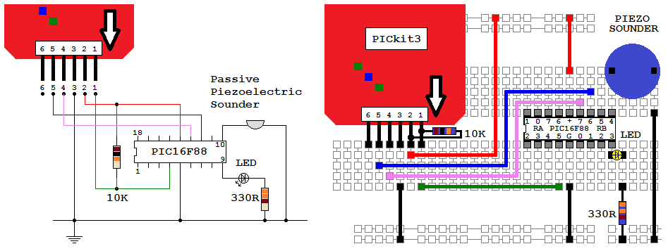
This program uses the shoestring programmer to flash the LED at 10Hz, accurately timed. If necessary, remember to power the board from the USB cable.
It uses XORWF, not mentioned in the WJEC/Eduqas sample assessment material. XOR is useful for inverting selected bits and leaving others unchanged.
Here is the measured 10.08 Hz, less than 1% out.
; PIC16F88 Configuration Bit Settings
; CONFIG1 and CONFIG2
#include "p16F88.inc"
 __CONFIG _CONFIG1, _FOSC_INTOSCIO & _WDTE_OFF & _PWRTE_OFF & _MCLRE_OFF & _BOREN_OFF & _LVP_OFF & _CPD_OFF & _WRT_OFF & _CCPMX_RB0 & _CP_OFF
 __CONFIG _CONFIG2, _FCMEN_ON & _IESO_ON

RES_VECT  CODE    0x0000            ; processor reset to vector address zero
    GOTO    START                   ; go to beginning of program

MAIN_PROG CODE                      ; let linker place main program

START:				    ; INITIALISATION
    bcf	    STATUS,	RP0         ; Select bank 0.
    movlw   b'00000000'		    ; Clear PORTA and PORTB (Never leave this to chance)
    movwf   PORTA
    movwf   PORTB

    bsf	    STATUS,	RP0         ; Select bank 1.
    movlw   b'00000000'		    ; Set all port pins to output / Disable ADC / Set for digital i/o
    movwf   ADCON1		    ; Disble ADC module (Never leave this to chance)
    movwf   ANSEL		    ; Set analog i/o for digital i/o (Never leave this to chance)
    movwf   TRISA		    ; Set porta for output - RA5 is input only so this bit is ignored
    movwf   TRISB		    ; Set portb for output

				    ; SET CLOCK TO 4 MHz or One Instruction per Microsecond
    movlw   b'01100000'		    ; <<<< Set Oscillator to 4 MHz or
    movwf   OSCCON		    ; <<<< one microsecond per line of code.

    CLRWDT			    ; Clear the Watchdog Timer and prescaler
    movlw   b'00000111'		    ; 1:256 prescaler for a delay of: (insruction-cycle * 256-counts)*prescaler = ((1uS * 256)*256) =~ 65.5 mS
				    ; ----0--- means the prescaler is assigned to Timer0
				    ; -----111 means the prescaler is set to 1:256
    movwf   OPTION_REG		    ;  The prescaler settings are stored here

    bcf	    STATUS,	RP0         ; Select bank 0.

PollingLoop:
    NOP
    NOP				    ; Do a whole lot more work here. But the timed event might happen late.
    NOP
    btfss   INTCON, TMR0IF	    ; did TMR0 roll over yet?
    goto    PollingLoop		    ; NO - Go back and repeat the PollingLoop.
    bcf	    INTCON, TMR0IF	    ; YES - Remember to clear the TMR0IF flag
    MOVLW   d'61'		    ; 61 was calculated to get 10 Hz Flash from the LED
    MOVWF   TMR0		    ; TMR0 now counts from 61 to 256 before setting the timer flag
				    ; 1 us * (256 - 61) * 256 = 49.9 ms   =~50 ms

    MOVLW   0xFF		    ; XOR with b'11111111' inverts all the bits (except RA5 which is input only)
    XORWF   PORTA		    ; Invert PORTA    50 ms ON time plus 50 ms OFF time
    XORWF   PORTB		    ; Invert PORTB    Period = 50 + 50 = 100 ms    Freq = 10 Hz

    GOTO    PollingLoop		    ; continue forever

    end
Contact, Copyright, Cookies and Legalities: C Neil Bauers - reviseOmatic V4 - © 2016 to 2026
Hosted at Akamai Cloud - London
Please report website problems to Neil