WANTED: Individual or team to take over this project. I'm in my 70's and want to put my feet up. Contact details in footer.
PIC16F88 0D Multiplex |
|
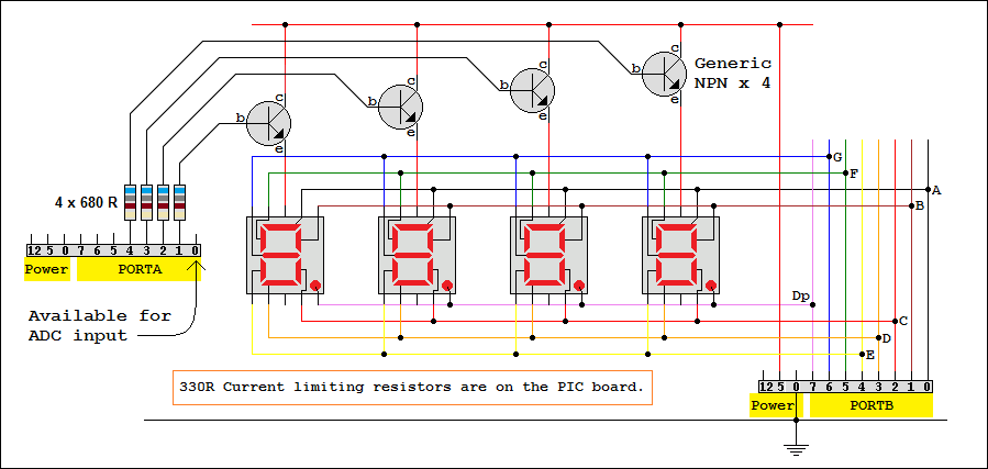
PORTA selects one of the four displays by setting the appropriate pin high.
PORTB lights the wanted segments on the selected display by setting the appropriate pin/s low.
If all four segments are used, they are each active 25% of the time. This makes the display dimmer than it might otherwise be.
To cure this disadvantage, the data would need to be latched for each display, adding complexity to the circuit.
The current could be quadrupled but not without blowing the microcontroller. High current drivers could be added though.
This program activates each display for about 0. 25 ms every 1 ms. This is a frame rate of 1000 Hz.
Flicker becomes noticeable below 50 Hz and intrusive below 25 Hz.
It's often useful to have a quick and dirty program to test the hardware. This one activates each segment in turn slowly enough to see if each one lights up.
;*******************************************************************************
; INPUT:    None.
; PROCESS:  One by one, activate each of the 32 display segments.
;	    Repeat the test for ever.
; OUTPUT:   One LED at a time will light up. Every LED should flash once.
;*******************************************************************************
; PIC16F88 Configuration Bit Settings
;*******************************************************************************
#include "p16f88.inc"
; CONFIG1 and CONFIG2
 __CONFIG _CONFIG1, _FOSC_INTOSCIO & _WDTE_OFF & _PWRTE_OFF & _MCLRE_OFF & _BOREN_ON & _LVP_OFF & _CPD_OFF & _WRT_OFF & _CCPMX_RB0 & _CP_OFF
 __CONFIG _CONFIG2, _FCMEN_ON & _IESO_ON

;*******************************************************************************
; Uninitialised Data - Reserve bytes here ...
;*******************************************************************************
    UDATA
DelCount    RES	    1		    ; reserves 1 byte - OK with simulator run-time watch

RES_VECT  CODE    0x0000            ; processor reset to vector address zero
    GOTO    START                   ; go to beginning of program

MAIN_PROG CODE                      ; let linker place main program

START:				    ; INITIALISATION
    bsf	    STATUS,	RP0         ; Select bank 1.
    movlw   b'00000000'		    ; Set all port pins to output / Disable ADC / Set for digital i/o
    movwf   ADCON1		    ; Disble ADC module (Never leave this to chance)
    movwf   ANSEL		    ; Set analog i/o for digital i/o (Never leave this to chance)
    movwf   TRISA		    ; Set porta - RA5 is input only so this bit is ignored
    movwf   TRISB		    ; Set portb

    bcf	    STATUS,	RP0         ; Select bank 0.

MYREPEAT:
    MOVLW   0x2			    ; Left hand segments
    MOVWF   PORTA		    ; Multiplex port output
    CALL    test_display

    MOVLW   0x4			    ; Second segments
    MOVWF   PORTA		    ; Multiplex port output
    CALL    test_display

    MOVLW   0x8			    ; Third segments
    MOVWF   PORTA		    ; Multiplex port output
    CALL    test_display

    MOVLW   0x10		    ; Right hand segments
    MOVWF   PORTA		    ; Multiplex port output
    CALL    test_display

    GOTO    MYREPEAT

;*******************************************************************************
; Test Segments
;*******************************************************************************
test_display:
    MOVLW   0xFE		    ; Segment A
    MOVWF   PORTB		    ; Multiplex port output
    CALL    MyDelay
    MOVLW   0xFD		    ; Segment B
    MOVWF   PORTB		    ; Multiplex port output
    CALL    MyDelay
    MOVLW   0xFB		    ; Segment C
    MOVWF   PORTB		    ; Multiplex port output
    CALL    MyDelay
    MOVLW   0xF7		    ; Segment D
    MOVWF   PORTB		    ; Multiplex port output
    CALL    MyDelay
    MOVLW   0xEF		    ; Segment E
    MOVWF   PORTB		    ; Multiplex port output
    CALL    MyDelay
    MOVLW   0xDF		    ; Segment F
    MOVWF   PORTB		    ; Multiplex port output
    CALL    MyDelay
    MOVLW   0xBF		    ; Segment G
    MOVWF   PORTB		    ; Multiplex port output
    CALL    MyDelay
    MOVLW   0x7F		    ; Segment Decimal Point
    MOVWF   PORTB		    ; Multiplex port output
    CALL    MyDelay
    MOVLW   0xFF		    ; Blank Display
    MOVWF   PORTB		    ; Multiplex port output
    CALL    MyDelay
    RETURN

;*******************************************************************************
; Count down from 255 to zero and execute some NOPs to slow everything down.
;*******************************************************************************
MyDelay:
    MOVLW   0xFF
    MOVWF   DelCount
MyDeloop:
    NOP
    NOP
    NOP
    NOP
    DECFSZ  DelCount, F
    GOTO    MyDeloop
    RETURN

    END
;*******************************************************************************
; PIC16F88 Configuration Bit Settings
;*******************************************************************************
    #include "p16F88.inc"
; CONFIG1 - Internal oscillator - Want I/O - Everything else turned off
 __CONFIG _CONFIG1, _FOSC_INTOSCIO & _WDTE_OFF & _PWRTE_OFF & _MCLRE_OFF & _BOREN_OFF & _LVP_OFF & _CPD_OFF & _WRT_OFF & _CCPMX_RB0 & _CP_OFF
; CONFIG2 - Turn on both
 __CONFIG _CONFIG2, _FCMEN_ON & _IESO_ON

;*******************************************************************************
; Uninitialised Data - Reserve bytes here ...
;*******************************************************************************
	    UDATA
ones	    RES	    1	; reserves 1 byte - OK with simulator run-time watch
tens	    RES	    1
hundreds    RES	    1
thousands   RES	    1
DelCount    RES	    1
PortaTemp   RES	    1	; To save and restore PORTA during the interrupt

;*******************************************************************************
; RESET VECTOR
;*******************************************************************************
RES_VECT    CODE 0x0000		; processor reset vector
	    GOTO CODE_INIT      ; beginning of program, initialise stuff

;*******************************************************************************
; INTERRUPT HANDLING
;*******************************************************************************
ISR	    CODE 0x0004		; The interrupt vector location is always 0x0004
	    GOTO ISR_HANDLER	; Jump to the Interrupt handling code

;*******************************************************************************
; MAIN PROGRAM - CODE INITIALISATION
;*******************************************************************************
MAIN_PROG   CODE	    ; let linker place main program

CODE_INIT:		    ; INITIALISATION
    CALL    CLOCK_INIT	    ; Set the clock frequency
    CALL    PORT_INIT	    ; Set up I/O Port Directions
    CALL    VAR_INIT	    ; Initialise Variable/s
    CALL    TIMER_INIT	    ; Set up Timer0
    CALL    TIMER_START	    ; Start Timer0

    BANKSEL PORTA	    ; Clear RP0 in STATUS to select Memory Bank 0
    GOTO    MUX_Loop	    ; Jump to Infinite Loop to Multiplex the Displays

;*******************************************************************************
; INTERRUPT SUBROUTINE
;     This ought to save and restore the complete context
;     In this example PORTA must be saved and restored
;*******************************************************************************
ISR_HANDLER:
    MOVWF   PortaTemp	    ; Save PORTA - Prevent display glitches
    CALL    IncCounter	    ; Add one to the four digit counter
    CALL    TIMER_START	    ; Start Timer0
    MOVF    PortaTemp, W    ; Restore PORTA - Prevent display glitches
    RETFIE		    ; Return from interrupt

;*******************************************************************************
; INITIALISE CLOCK FREQUENCY - 4MHz - 1 microsecond per instruction
;*******************************************************************************
CLOCK_INIT:
    BANKSEL OSCCON
    movlw   b'01100000'	    ; -110----    4 MHz
    movwf   OSCCON	    ; At 4 MHz it's one microsecond per line of code.
    RETURN

;*******************************************************************************
; INITIALISE PORTS
;*******************************************************************************
PORT_INIT:
    BANKSEL TRISA	    ; Set RP0 in STATUS to select Memory Bank 1
    MOVLW   b'00000000'	    ; Disable ADC / Set for digital i/o
    MOVWF   ADCON1	    ; Disble ADC module (Never leave this to chance)
    MOVWF   ANSEL	    ; Turn off analog i/o. Select digital i/o (Never leave this to chance)

    MOVLW   b'00000000'	    ; Eight output lines
    MOVWF   TRISA	    ; Set PORTA as Outputs - Remember RA5 is input only
    MOVWF   TRISB	    ; Set PORTB as Outputs
    RETURN

;*******************************************************************************
; INITIALISE VARIABLES
;*******************************************************************************
VAR_INIT:
    BANKSEL PORTA	    ; Clear RP0 in STATUS to select Memory Bank 0
    MOVLW   d'0'.           ; Initial value
    MOVWF   ones	    ; initialise to zero
    MOVLW   d'0'            ; Just in case we don't want another zero
    MOVWF   tens	    ; initialise to zero
    MOVLW   d'0'
    MOVWF   hundreds	    ; initialise to zero
    MOVLW   d'0'
    MOVWF   thousands	    ; initialise to zero
    RETURN

;*******************************************************************************
; INITIALISE TIMER0
;*******************************************************************************
TIMER_INIT:
    BANKSEL TRISA	    ; Set RP0 in STATUS to select Memory Bank 1
    CLRWDT		    ; Clear the Watchdog Timer and prescaler
    MOVLW   b'00000110'	    ; 1:64 TMR0 rate prescaling - If simulating reduce to 1:4 or 1:8
    MOVWF   OPTION_REG	    ; The prescaler settings are stored in OPTION_REG

    BSF	    INTCON, GIE	    ; Turn on interupts globally
    BSF	    INTCON, TMR0IE  ; Turn on Timer0 interupts
    RETURN

;*******************************************************************************
; START TIMER
;*******************************************************************************
TIMER_START:
    BANKSEL PORTA	    ; Clear RP0 in STATUS to select Memory Bank 0
    BCF	    INTCON, TMR0IF  ; Clear the TMR0IF flag
    MOVLW   d'10'	    ; TMR0 counts from 10 to 256 - If simulating, 250 might be better
    MOVWF   TMR0	    ; 10 copied into TMR0
    RETURN

;*******************************************************************************
; MUX_Loop sends the multiplexed binary to the four displays
; At regular intervals, it's interrupted and one is added to the counter
;*******************************************************************************
MUX_Loop:
    MOVLW   0x0		    ; Blank digit - prevent display glitches
    MOVWF   PORTA
    MOVF    ones, W	    ; Copy the ones digit into WREG
    CALL    SEV_SEG	    ; Return the binary to light the segments into WREG
    MOVWF   PORTB
    MOVLW   0x10	    ; Show right hand digit by
    MOVWF   PORTA	    ; copying 0x10 to PORTA

    MOVLW   0x30
    MOVWF   DelCount
Deloop1:
    NOP
    NOP
    DECFSZ  DelCount, F
    GOTO    Deloop1

    MOVLW   0x0		    ; Blank second digit - prevent display glitches
    MOVWF   PORTA
    MOVF    tens, W	    ; Copy the tens digit into WREG
    CALL    SEV_SEG	    ; Return the binary to light the segments into WREG
    MOVWF   PORTB
    MOVLW   0x8		    ; Show second digit by
    MOVWF   PORTA	    ; copying 0x8 to PORTA

    MOVLW   0x30
    MOVWF   DelCount
Deloop2:
    NOP
    NOP
    DECFSZ  DelCount, F
    GOTO    Deloop2

    MOVLW   0x0		    ; Blank third digit - prevent display glitches
    MOVWF   PORTA
    MOVF    hundreds, W	    ; Copy the hundreds digit into WREG
    CALL    SEV_SEG	    ; Return the binary to light the segments into WREG
    MOVWF   PORTB
    MOVLW   0x4		    ; Show third digit by
    MOVWF   PORTA	    ; copying 0x4 to PORTA

    MOVLW   0x30
    MOVWF   DelCount
Deloop3:
    NOP
    NOP
    DECFSZ  DelCount, F
    GOTO    Deloop3

    MOVLW   0x0		    ; Blank left digit - prevent display glitches
    MOVWF   PORTA
    MOVF    thousands, W    ; Copy the thousands digit into WREG
    CALL    SEV_SEG	    ; Return the binary to light the segments into WREG
    MOVWF   PORTB
    MOVLW   0x2		    ; Show left hand digit by
    MOVWF   PORTA	    ; copying 0x2 to PORTA

    MOVLW   0x30
    MOVWF   DelCount
Deloop4:
    NOP
    NOP
    DECFSZ  DelCount, F
    GOTO    Deloop4

    GOTO    MUX_Loop

;*******************************************************************************
; Add one to the four digit counter. If it was on 9999 reset it to zero
;*******************************************************************************
IncCounter:
Ones:
    INCF    ones
    MOVLW   d'10'
    SUBWF   ones, W
    BTFSS   STATUS, Z	; Will be set if ones has reached 10
    RETURN		; No need to do the rest
Tens:
    MOVLW   0x00
    MOVWF   ones	; Reset ones to zero
    INCF    tens
    MOVLW   d'10'
    SUBWF   tens, W
    BTFSS   STATUS, Z	; Will be set if tens has reached 100
    RETURN		; No need to do the rest
Hundreds:
    MOVLW   0x00
    MOVWF   tens	; Reset tens to zero
    INCF    hundreds
    MOVLW   d'10'
    SUBWF   hundreds, W
    BTFSS   STATUS, Z	; Will be set if hundreds has reached 1000
    RETURN		; No need to do the rest
Thousands:
    MOVLW   0x00
    MOVWF   hundreds	; Reset hundreds to zero
    INCF    thousands
    MOVLW   d'10'
    SUBWF   thousands, W
    BTFSS   STATUS, Z	; Will be set if thousands has reached 10000
    RETURN		; No need to do the rest
    MOVLW   0x00
    MOVWF   thousands	; Reset thousands to zero
    RETURN

;*******************************************************************************
; DATA TABLE FOR THE SEVEN SEGMENT DISPLAY
; INPUT:	The table position in WREG
; PROCESS:	Add WREG to PCL. It's like "GOTO Table Position"
; OUTPUT:	Return the data using RETLW
;*******************************************************************************
SEV_SEG:
    addwf PCL, 1    ; GOTO table position and Return the byte in the WREG
    retlw 0xC0	    ; 0 - Turn on the correct segments to show a zero
    retlw 0xF9	    ; 1
    retlw 0xA4	    ; 2
    retlw 0xB0	    ; 3
    retlw 0x99	    ; 4
    retlw 0x92	    ; 5
    retlw 0x82	    ; 6
    retlw 0xF8	    ; 7
    retlw 0x80	    ; 8
    retlw 0x98	    ; 9
    retlw 0x7F	    ; Decimal Point

    END
Contact, Copyright, Cookies and Legalities: C Neil Bauers - reviseOmatic V4 - © 2016 to 2026
Hosted at Akamai Cloud - London
Please report website problems to Neil