PIC16F88 04 OSCCON |
|
This program uses the shoestring programmer. If necessary, remember to power the board from the USB cable.
This is the LED flasher and Buzzer program with a 4MHz clock.
With this clock frequency, each line of code takes one microsecond.
GOTO, CALL and RETURN each take two microseconds.
Lots of (badly written) time delay code is needed to get the buzzer output down to the range for human hearing.
Without the delays the output would be an ultrasonic signal at 100 kHz.
It's more efficient to use the timers built into the chip but that's for another lesson.
This example uses Subroutines (Good style). A subroutine is like a small self contained program within the larger program. It should perform a single task that's needed more than once or many times in the program. Frequently used subroutines can be put into a library. Then you don't need to re-invent the wheel every time you write a program. Just use the library subroutine. Well named subroutines make complex programs much easier to understand. Subroutines allow the program to be modularised. This makes code testing and debugging easier.
The line marked "<<<<" sets the clock to 4MHz.
; PIC16F88 Configuration Bit Settings
; CONFIG1 and CONFIG2
#include "p16F88.inc"
 __CONFIG _CONFIG1, _FOSC_INTOSCIO & _WDTE_OFF & _PWRTE_OFF & _MCLRE_OFF & _BOREN_OFF & _LVP_OFF & _CPD_OFF & _WRT_OFF & _CCPMX_RB0 & _CP_OFF
 __CONFIG _CONFIG2, _FCMEN_ON & _IESO_ON

RES_VECT  CODE    0x0000            ; processor reset to vector address zero
    GOTO    START                   ; go to beginning of program

MAIN_PROG CODE                      ; let linker place main program

START:				    ; INITIALISATION
    bsf	    STATUS,	RP0         ; Select bank 1.
    movlw   b'00000000'		    ; Set all port pins to output / Disable ADC / Set for digital i/o
    movwf   ADCON1		    ; Disble ADC module (Never leave this to chance)
    movwf   ANSEL		    ; Set analog i/o for digital i/o (Never leave this to chance)
    movwf   TRISA		    ; Set porta for output - RA5 is input only so this bit is ignored
    movwf   TRISB		    ; Set portb for output

				    ; Set OSCCON bits for the internal RC oscillator clock
;   movlw   b'00000000'		    ;   31.25 kHz
;   movlw   b'00010000'		    ;  125    kHz
;   movlw   b'00100000'		    ;  250    kHz
;   movlw   b'00110000'		    ;  500    kHz
;   movlw   b'01000000'		    ;    1    MHz
;   movlw   b'01010000'		    ;    2    MHz
    movlw   b'01100000'		    ;    4    MHz <<<< THIS ONE IS ACTIVE
;   movlw   b'01110000'		    ;    8    MHz
    movwf   OSCCON		    ; At 4 MHz it's one microsecond per line of code.

    bcf	    STATUS,	RP0         ; Select bank 0.

MYREPEAT:                           ; NOP padded to take 20 microseconds
    movlw   0xFF		    ; Toggle all the pins ON
    movwf   PORTA		    ; Move the byte to PORTA
    movwf   PORTB		    ; Move the byte to PORTB - but not RA5 which is input only.
    call    MYDELAY		    ; 92 microseconds - Comment this out to run it in the simulator
    nop				    ; No-Operation, Needed for timing
    nop				    ; to get a square wave output
    nop				    ; to get a square wave output
    nop				    ; to get a square wave output - 101 uS to here

    movlw   0x00		    ; Toggle all the pins OFF
    movwf   PORTA		    ; Move the byte to PORTA
    movwf   PORTB		    ; Move the byte to PORTB
    call    MYDELAY		    ; 92 microseconds - Comment this out to run it in the simulator
    nop				    ; to get a square wave output

    GOTO    MYREPEAT		    ; Jump (two clock cycles matching the nop lines above)
				    ; Total time is 200 plus one extra NOP to get exactly 5000 Hz

MYDELAY:
    CALL MOREDELAY		    ; The call takes 2 microseconds - MOREDELAY takes 8 = 10 total
    CALL MOREDELAY
    CALL MOREDELAY
    CALL MOREDELAY
    CALL MOREDELAY
    CALL MOREDELAY
    CALL MOREDELAY
    CALL MOREDELAY
    CALL MOREDELAY
    RETURN			    ; 92 microseconds by running MOREDELAY nine times + 2 for the RETURN

MOREDELAY:			    ; 8 microseconds for this subroutine
    NOP
    NOP
    NOP
    NOP
    NOP
    NOP
    RETURN

    END
           Clock Freqency  Instruction Cycle Period
x000----    31.25 kHz      128 microseconds - The default
x001----   125    kHz       32 microseconds
x010----   250    kHz       16 microseconds
x011----   500    kHz        8 microseconds
x100----     1    MHz        4 microseconds
x101----     2    MHz        2 microseconds
x110----     4    MHz        1 microsecond - Easy to work out timings
x111----     8    MHz      500 nanoseconds
------00   means the clock mode is determined by the FOSC configuration
-----1--   1 means the frequency is stable
----0---   0 means it's running from INTRC, the internal RC oscillator
-111----   Three bits to set the frequency to one of 8 values - see table above
x-------   Not used
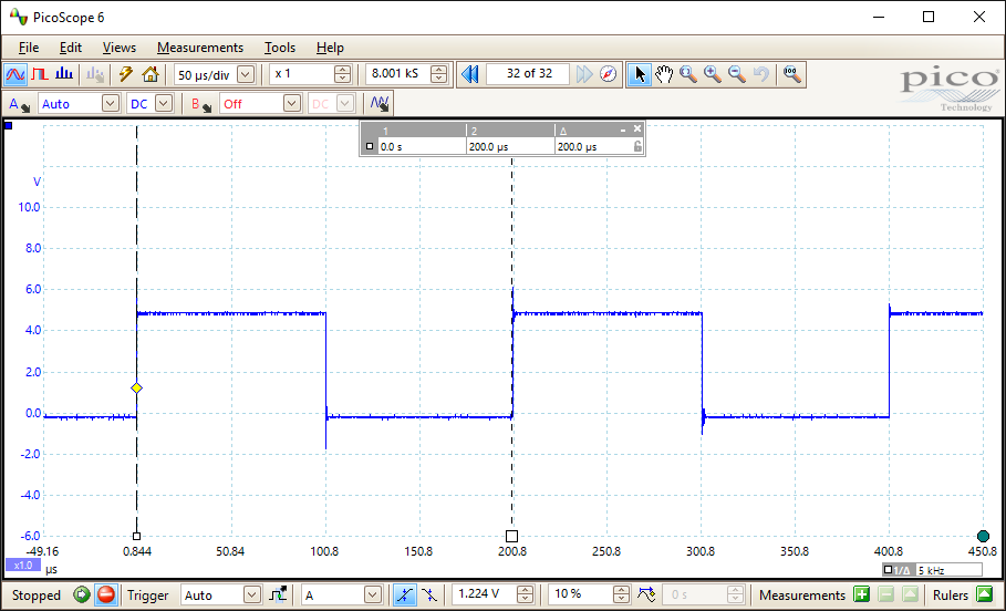
The program was written to get a frequency of 5000 Hz. Here is a measured 5000 Hz. One NOP was added to correct the timing. The OCSTUNE register could be tweaked instead.
Contact, Copyright, Cookies and Legalities: C Neil Bauers - reviseOmatic V4 - © 2016/17
Hosted at linode.com - London
Please report website problems to Neil