WANTED: Individual or team to take over this project. I'm in my 70's and want to put my feet up. Contact details in footer.
PIC16F88 07 Traffic Lights |
|
This example can be applied to any digital output scenario like controling a seven segment display, a LED matrix display or a stepper motor.
The only difference is the timing and the control data values.
Of course motors would need their own drivers as this chip lacks the power.
The LEDs are wired with common cathodes so a logic one is needed to light each LED.
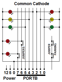
The PICkit3 programmer needs to use RA5, RB6 and RB7 for re-programming.
This LED board has been designed so these pins can be left available for the programmer.
RA5 is not used at all. During programming, the LEDs on RB6 and RB7 should be disconnected using the jumpers.
These LEDs are not needed for the traffic lights simulation so they could be left disconnected.
They were included so this board can be used to test all the output pins on either PORTB or PORTA.
Remember that RA5 is input-only so don't expect the RA5 LED to light up during the PORTA test.
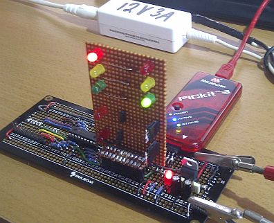
Having forgotten to disconnect the jumpers, the programmer worked OK.
It was interesting to see the LEDs on RB6 and RB7 light up during programming. This is not recommended though!
LED current limiting resistors are built into the Programmer Board and are not needed on the Traffic Lights plug-in.
Logic 1 turns on the LEDs. Lets have overlapping Red lights for safety.
| Bit | RB7 | RB6 | RB5 | RB4 | RB3 | RB2 | RB1 | RB0 | |
| 0x80 | 0x40 | 0x20 | 0x10 | 0x08 | 0x04 | 0x02 | 0x01 | ||
| Not Used | Not Used | Green | Amber | Red | Red | Amber | Green | Hex Value | |
| 0 | 0 | 1 | 0 | 0 | 1 | 0 | 0 | 0x24 | |
| 0 | 0 | 0 | 1 | 0 | 1 | 0 | 0 | 0x14 | |
| 0 | 0 | 0 | 0 | 1 | 1 | 0 | 0 | 0x0C | |
| 0 | 0 | 0 | 0 | 1 | 1 | 1 | 0 | 0x0E | |
| 0 | 0 | 0 | 0 | 1 | 0 | 0 | 1 | 0x09 | |
| 0 | 0 | 0 | 0 | 1 | 0 | 1 | 0 | 0x0A | |
| 0 | 0 | 0 | 0 | 1 | 1 | 0 | 0 | 0x0C | |
| 0 | 0 | 0 | 1 | 1 | 1 | 0 | 0 | 0x1C |
; PIC16F88 Configuration Bit Settings
; CONFIG1 and CONFIG2
#include "p16F88.inc"
 __CONFIG _CONFIG1, _FOSC_INTOSCIO & _WDTE_OFF & _PWRTE_OFF & _MCLRE_OFF & _BOREN_OFF & _LVP_OFF & _CPD_OFF & _WRT_OFF & _CCPMX_RB0 & _CP_OFF
 __CONFIG _CONFIG2, _FCMEN_ON & _IESO_ON

RES_VECT  CODE    0x0000            ; processor reset to vector address zero
    GOTO    START                   ; go to beginning of program

MAIN_PROG CODE                      ; let linker place main program

START:				    ; INITIALISATION
    bsf	    STATUS,	RP0         ; Select bank 1.
    movlw   b'00000000'		    ; Set all port pins to output / Disable ADC / Set for digital i/o
    movwf   ADCON1		    ; Disble ADC module (Never leave this to chance)
    movwf   ANSEL		    ; Set analog i/o for digital i/o (Never leave this to chance)
    movwf   TRISA		    ; Set porta for output - RA5 is input only so this bit is ignored
    movwf   TRISB		    ; Set portb for output

    movlw   b'00000000'		    ; <<<< Set Oscillator to 31.25 kHz or
    movwf   OSCCON		    ; <<<< 128 microseconds per line of code.

    CLRWDT			    ; Clear the Watchdog Timer and prescaler
    movlw   b'00000111'		    ; 1:256 prescaler for a delay of: (insruction-cycle * 256-counts)*prescaler = ((1uS * 256)*256) =~ 65.5 mS
				    ; ----0--- means the prescaler is assigned to Timer0
				    ; -----111 means the prescaler is set to 1:256
    movwf   OPTION_REG		    ;  The prescaler settings are stored in OPTION_REG

    bcf	    STATUS,	RP0         ; Select bank 0.

LIGHTS:				    ; 84218421
    MOVLW   0x24		    ; XXGARRAG
    MOVWF   PORTB		    ;   1  1
    CALL    DELAY
    CALL    DELAY		    ; Longer Delay
    CALL    DELAY
    CALL    DELAY
    CALL    DELAY
				    ; 84218421
    MOVLW   0x14		    ; XXGARRAG
    MOVWF   PORTB		    ;    1 1
    CALL    DELAY
				    ; 84218421
    MOVLW   0x0C		    ; XXGARRAG
    MOVWF   PORTB		    ;     11
    CALL    DELAY
				    ; 84218421
    MOVLW   0x0E		    ; XXGARRAG
    MOVWF   PORTB		    ;     111
    CALL    DELAY
				    ; 84218421
    MOVLW   0x09		    ; XXGARRAG
    MOVWF   PORTB		    ;     1  1
    CALL    DELAY
    CALL    DELAY		    ; Longer Delay
    CALL    DELAY
    CALL    DELAY
    CALL    DELAY
				    ; 84218421
    MOVLW   0x0A		    ; XXGARRAG
    MOVWF   PORTB		    ;     1 1
    CALL    DELAY
				    ; 84218421
    MOVLW   0x0C		    ; XXGARRAG
    MOVWF   PORTB		    ;     11
    CALL    DELAY
				    ; 84218421
    MOVLW   0x1C		    ; XXGARRAG
    MOVWF   PORTB		    ;    111
    CALL    DELAY

    GOTO    LIGHTS		    ; continue forever

DELAY:
    bcf	    INTCON, TMR0IF	    ; Clear the TMR0IF flag
    MOVLW   d'222'		    ; 222 was calculated to get about 1s delay
    MOVWF   TMR0		    ; TMR0 now counts from 222 to 256 before setting the timer flag
				    ; 128 us * (256 - 222) * 256 =~ 1s
DELAY_POLL:
    btfss   INTCON, TMR0IF	    ; did TMR0 roll over yet? Is TMR0IF set?
    goto    DELAY_POLL		    ; NO - Go back and repeat the DELAY_POLL polling loop.
    RETURN			    ; YES - Return from the subroutine

    end
Contact, Copyright, Cookies and Legalities: C Neil Bauers - reviseOmatic V4 - © 2016 to 2025
Hosted at Akamai Cloud - London
Please report website problems to Neil