PIC16F88 0B Digital I/O |
|
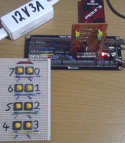
The program polls PORTA and copies the input data to PORTB.
All the output LEDs are off untill a push button is pressed.
The polling is triggered by a Timer0 interrupt.
It's interesting to run this code with the switch board unplugged.
The floating inputs pick up random data from the electrical noise in the environment so the output LEDs flash unpredictably.
Never leave floating inputs!
;*******************************************************************************
; PIC16F88 Configuration Bit Settings
;*******************************************************************************
#include "p16F88.inc"
; CONFIG1
 __CONFIG _CONFIG1, _FOSC_INTOSCIO & _WDTE_OFF & _PWRTE_OFF & _MCLRE_OFF & _BOREN_OFF & _LVP_OFF & _CPD_OFF & _WRT_OFF & _CCPMX_RB0 & _CP_OFF
; CONFIG2
 __CONFIG _CONFIG2, _FCMEN_ON & _IESO_ON

;*******************************************************************************
; Uninitialised Data - Reserve bytes here ...
;*******************************************************************************
	    UDATA
PortByte    RES	1		; reserves 1 byte - OK with simulator debug

;*******************************************************************************
; RESET VECTOR
;*******************************************************************************
RES_VECT    CODE 0x0000		; processor reset vector
	    GOTO    CODE_INIT   ; beginning of program, initialise stuff

;*******************************************************************************
; INTERRUPT HANDLING
;*******************************************************************************
ISR	    CODE 0x0004		; The interrupt vector location is always 0x0004
	    GOTO    ISR_HANDLER	; Jump to the Interrupt handling code

;*******************************************************************************
; MAIN PROGRAM - CODE INITIALISATION
;*******************************************************************************
MAIN_PROG   CODE	    ; let linker place main program

CODE_INIT:		    ; INITIALISATION
    CALL    PORT_INIT	    ; Set up I/O Port Directions
    CALL    TIMER_INIT	    ; Set up Timer0
    CALL    TIMER_START	    ; Start Timer0
    GOTO    IDLE_LOOP	    ; Jump to the Infinite Idle Loop

;*******************************************************************************
; INTERRUPT SUBROUTINE
;     This ought to save and restore the context
;     It's not secessary in this simple example
;*******************************************************************************
ISR_HANDLER:
    BCF	    STATUS, RP0     ; Select memory bank 0.
    MOVF    PORTA, 0	    ; Copy PORTA to WREG
    MOVWF   PortByte
    CALL    SET_PORTB
    CALL    TIMER_START	    ; Re-Start Timer0
    RETFIE		    ; Return from interrupt

;*******************************************************************************
; INITIALISE PORTS
;*******************************************************************************
PORT_INIT:	    ; Use PIC16F88 Data Sheet method
    BANKSEL PORTA   ; select bank of PORTA (Bank 1)
    CLRF    PORTA   ; Initialize PORTA by
		    ; clearing output
		    ; data latches

    BANKSEL ANSEL   ; Select Bank of ANSEL
    MOVLW   0x00    ; Configure all pins
    MOVWF   ANSEL   ; as digital inputs

    MOVLW   0xFF    ; Value used to initialize data direction (8 Inputs)
    MOVWF   TRISA   ; Set RA<7:0> as inputs

    MOVLW   0x00    ; Value used to initialize data direction (8 Outputs)
    MOVWF   TRISB   ; Set RA<7:0> as out6puts

    RETURN

;*******************************************************************************
; INITIALISE TIMER0
;*******************************************************************************
TIMER_INIT:
    BSF	    STATUS, RP0	    ; Select memory bank 1.
    CLRWDT		    ; Clear the Watchdog Timer and prescaler
    MOVLW   b'00000010'	    ; 1:8 Prescaling
    MOVWF   OPTION_REG	    ; The prescaler settings are stored in OPTION_REG

    BSF	    INTCON, GIE	    ; Turn on interupts globally
    BSF	    INTCON, TMR0IE  ; Turn on Timer0 interupts
    RETURN

;*******************************************************************************
; START TIMER
;*******************************************************************************
TIMER_START:
    BCF	    STATUS, RP0     ; Select memory bank 0.
    BCF	    INTCON, TMR0IF  ; Clear the TMR0IF flag
    MOVLW   d'250'	    ; TMR0 counts from 250 to 256
    MOVWF   TMR0	    ; 250 copied into TMR0
    RETURN

;*******************************************************************************
; Send data to the ports
;*******************************************************************************
SET_PORTB:
    BCF	    STATUS, RP0     ; Select memory bank 0.
    MOVF    PortByte, 0	    ; Copy MyCount to WREG
    MOVWF   PORTB	    ; Copy WREG to PORTB
    RETURN

;*******************************************************************************
; The Idle Loop
; MS Windows has an "idle process" which waits for the user to do something.
;*******************************************************************************
IDLE_LOOP:
    NOP
    NOP	; NOPs make the code execution obvious in the simulator
    NOP	; Leave them out in real life
    NOP
    GOTO    IDLE_LOOP

    END
Contact, Copyright, Cookies and Legalities: C Neil Bauers - reviseOmatic V4 - © 2016/17
Hosted at linode.com - London
Please report website problems to Neil