PIC16F88 02 MPLAB X |
|
MPLAB X Downloads, Documentation and User Guide - This is the integrated development environment for programming microchip.com devices.
MPASM User's Guide - Find out what all those obscure mnemonics and directives mean.
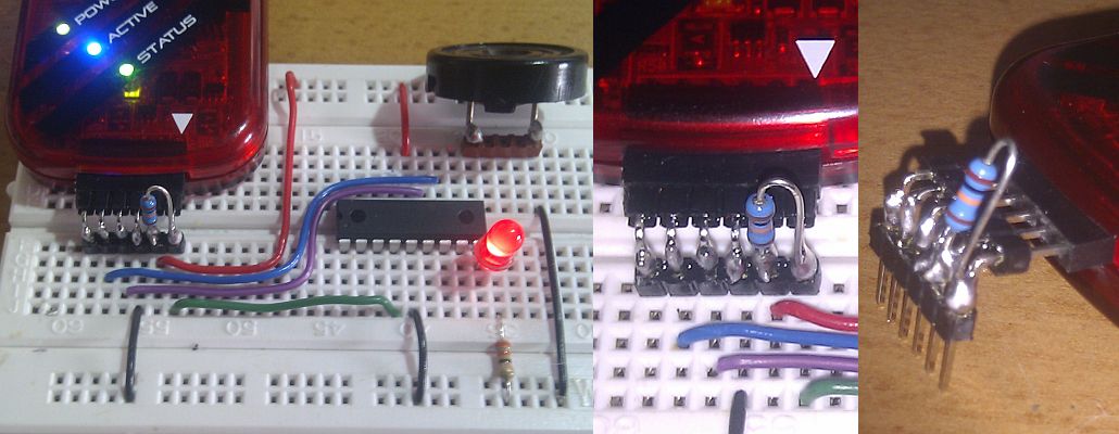
This uses the PICkit3. If you use the the shoestring PIC16F88 programmer, remember to power the board from the USB cable.
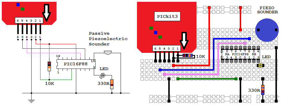
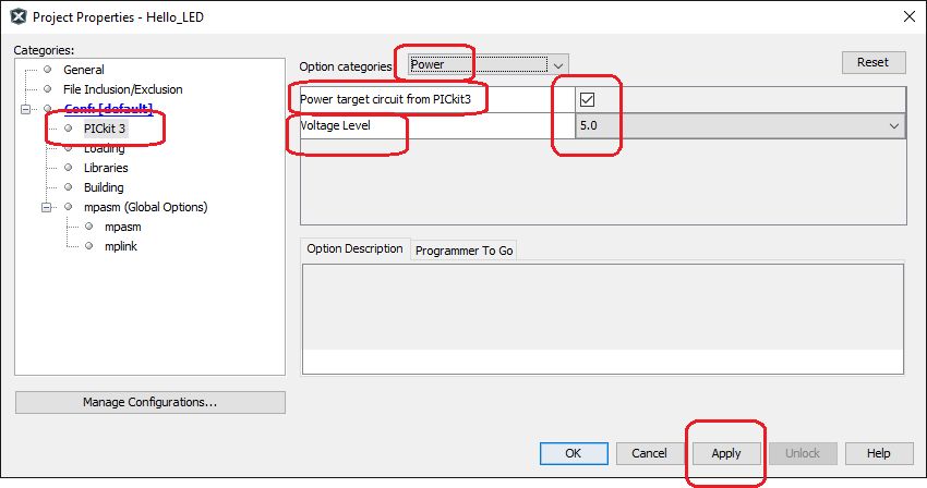
File ↠ Project Properties ↠ Set it up like this. There is a 20 mA current limit (a couple of LEDs).
This was written using MPLAB-X and the built-in wizards for setting the configuration registers. Or copy the code below and paste it in.
The program flashes the LED (too fast to see the flicker) and drives the sounder which whines at 850 Hz. To slow the program down enough to see the LED flickering, time delay code will be needed.
; PIC16F88 Configuration Bit Settings
#include "p16f88.inc"
; CONFIG1 and CONFIG2
 __CONFIG _CONFIG1, _FOSC_INTOSCIO & _WDTE_OFF & _PWRTE_OFF & _MCLRE_OFF & _BOREN_ON & _LVP_OFF & _CPD_OFF & _WRT_OFF & _CCPMX_RB0 & _CP_OFF
 __CONFIG _CONFIG2, _FCMEN_ON & _IESO_ON

RES_VECT  CODE    0x0000            ; processor reset to vector address zero
    GOTO    START                   ; go to beginning of program

MAIN_PROG CODE                      ; let linker place main program

START:				    ; INITIALISATION
    bsf	    STATUS,	RP0         ; Select bank 1.
    movlw   b'00000000'		    ; Set all port pins to output / Disable ADC / Set for digital i/o
    movwf   ADCON1		    ; Disble ADC module (Never leave this to chance)
    movwf   ANSEL		    ; Set analog i/o for digital i/o (Never leave this to chance)
    movwf   TRISA		    ; Set porta - RA5 is input only so this bit is ignored
    movwf   TRISB		    ; Set portb

    bcf	    STATUS,	RP0         ; Select bank 0.

MYREPEAT:
    movlw   0xFF		    ; Toggle all the pins ON
    movwf   PORTA		    ; Move the byte to PORTA - But not RA5 which is input only
    movwf   PORTB		    ; Move the byte to PORTB
    nop				    ; No-Operation, Needed for timing
    nop				    ; to get a square wave output

    movlw   0x00		    ; Toggle all the pins OFF
    movwf   PORTA		    ; Move the byte to PORTA - But not RA5 which is input only
    movwf   PORTB		    ; Move the byte to PORTB

    GOTO    MYREPEAT		    ; Jump (two clock cycles matching the two nop lines above)

    END
Here is a picoscope trace of the program output.
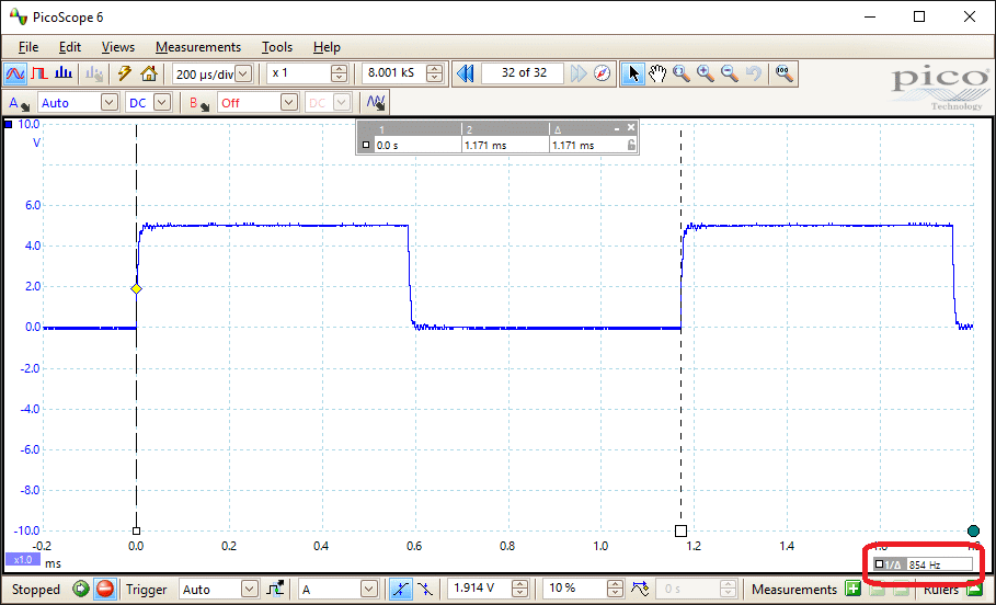
This program is about as simple as it's possible to get. The default, slowest clock frequency was used at 31.25 kHz which gives 7813 instruction cycles or lines of code per second.
Lines 1 to 10 will be very similar for every program you ever write. They set up the configuration bits and load a header file. Without this, you'd need to know the addresses and bit positions of all the chip registers. For example PORTA resides at address 0x05. Learning all these addresses for all the different types of chips would be near impossible.
Lines 12 to 20 set up the two ports for input or output and turn off the ADC.
Line 22 onwards does the actual work in 9 lines of code. Each line takes one instruction cycle except for the GOTO which takes two. So it takes 10 instruction cycles and 40 clock cycles to complete the loop.
These figures predict a buzzer frequency of 781 Hz. We measured 854 Hz. This is less than 10% out which is typical for the low quality RC oscillator built into the chip.
For more precise timing, an external crystal oscillator needs to be used.
Contact, Copyright, Cookies and Legalities: C Neil Bauers - reviseOmatic V4 - © 2016/17
Hosted at linode.com - London
Please report website problems to Neil