WANTED: Individual or team to take over this project. I'm in my 70's and want to put my feet up. Contact details in footer.
PIC16F88 0A Data Table |
|
The control data to make the display count is stored in a data table.
This PIC family has a neat feature where you can store the data table position into WREG and call a subroutine containing the data. The subroutine adds the table position to PCL, the program counter. The subroutine returns immediately with the data you need, stored in WREG. In small programs, this is easy. In larger programs that span more than one memory page, it's more of a brain teaser to get it to work. Google knows how. The technique uses RETLW. This is not mentioned in the WJEC/Eduqas sample assessment material but it's too useful to ignore, especially for project work.
This is the first example program where some effort has been made to structure the code better.
The code and data are separated.
The code is quite modular.
;*******************************************************************************
; PIC16F88 Configuration Bit Settings
;*******************************************************************************
#include "p16F88.inc"
; CONFIG1 - Internal oscillator - Want I/O - Everything else turned off
__CONFIG _CONFIG1, _FOSC_INTOSCIO & _WDTE_OFF & _PWRTE_OFF & _MCLRE_OFF & _BOREN_OFF & _LVP_OFF & _CPD_OFF & _WRT_OFF & _CCPMX_RB0 & _CP_OFF
; CONFIG2 - Turn on both
__CONFIG _CONFIG2, _FCMEN_ON & _IESO_ON
;*******************************************************************************
; Uninitialised Data - Reserve bytes here ...
;*******************************************************************************
UDATA
MyCount RES 1 ; reserves 1 byte - OK with simulator debug
;*******************************************************************************
; RESET VECTOR
;*******************************************************************************
RES_VECT CODE 0x0000 ; processor reset vector
GOTO CODE_INIT ; beginning of program, initialise stuff
;*******************************************************************************
; INTERRUPT HANDLING
;*******************************************************************************
ISR CODE 0x0004 ; The interrupt vector location is always 0x0004
GOTO ISR_HANDLER ; Jump to the Interrupt handling code
;*******************************************************************************
; MAIN PROGRAM - CODE INITIALISATION
;*******************************************************************************
MAIN_PROG CODE ; let linker place main program
CODE_INIT: ; INITIALISATION
CALL PORT_INIT ; Set up I/O Port Directions
CALL VAR_INIT ; Initialise Variable/s
CALL TIMER_INIT ; Set up Timer0
CALL TIMER_START ; Start Timer0
GOTO IDLE_LOOP ; Jump to the Infinite Idle Loop
;*******************************************************************************
; INTERRUPT SUBROUTINE
; This ought to save and restore the context
; It's not secessary in this simple example
;*******************************************************************************
ISR_HANDLER:
BCF STATUS, RP0 ; Select memory bank 0.
DECFSZ MyCount, 1 ; Decrement MyCount - result into MyCount
GOTO MY_COUNT_NOT_ZERO
CALL SET_PORTS
CALL VAR_INIT
RETFIE ; Return from interrupt
MY_COUNT_NOT_ZERO:
CALL SET_PORTS
RETFIE ; Return from interrupt
;*******************************************************************************
; INITIALISE PORTS
;*******************************************************************************
PORT_INIT:
BSF STATUS, RP0 ; Select memory bank 1.
MOVLW b'00000000' ; Disable ADC / Set for digital i/o
MOVWF ADCON1 ; Disble ADC module (Never leave this to chance)
MOVWF ANSEL ; Turn off analog i/o. Select digital i/o (Never leave this to chance)
MOVLW b'11111111' ; Eight Input lines
MOVWF TRISA ; Set PORTA as Inputs - Remember RA5 is input only
MOVLW b'00000000' ; Eight output lines
MOVWF TRISB ; Set PORTB as outputs
RETURN
;*******************************************************************************
; INITIALISE VARIABLES
;*******************************************************************************
VAR_INIT:
BCF STATUS, RP0 ; Select memory bank 0.
MOVLW 0x0B ; Initialise MyCount
MOVWF MyCount ; to d'11'
RETURN
;*******************************************************************************
; INITIALISE TIMER0
;*******************************************************************************
TIMER_INIT:
BSF STATUS, RP0 ; Select memory bank 1.
CLRWDT ; Clear the Watchdog Timer and prescaler
MOVLW b'00000110' ; 1:64 TMR0 rate prescaling - If simulating reduce to 1:4 or 1:8
MOVWF OPTION_REG ; The prescaler settings are stored in OPTION_REG
BSF INTCON, GIE ; Turn on interupts globally
BSF INTCON, TMR0IE ; Turn on Timer0 interupts
RETURN
;*******************************************************************************
; START TIMER
;*******************************************************************************
TIMER_START:
BCF STATUS, RP0 ; Select memory bank 0.
BCF INTCON, TMR0IF ; Clear the TMR0IF flag
MOVLW d'220' ; TMR0 counts from 220 to 256 - If simulating, 250 might be better
MOVWF TMR0 ; 220 copied into TMR0
RETURN
;*******************************************************************************
; Send data to the ports
;*******************************************************************************
SET_PORTS:
BCF STATUS, RP0 ; Select memory bank 0.
MOVF MyCount, 0 ; Copy MyCount to WREG
CALL SEV_SEG ; Returns with WREG containing a control byte
MOVWF PORTB ; Copy WREG to PORTB
CALL TIMER_START ; Re-start the timer
RETURN
;*******************************************************************************
; The Idle Loop
; MS Windows has an "idle process" which waits for the user to do something.
;*******************************************************************************
IDLE_LOOP:
NOP
NOP ; NOPs make the code execution obvious in the simulator
NOP ; Leave them out in real life
NOP
GOTO IDLE_LOOP
;*******************************************************************************
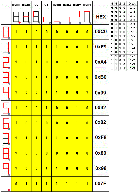
; DATA FOR THE SEVEN SEGMENT DISPLAY - Must not cross a page boundary
;*******************************************************************************
SEV_SEG:
addwf PCL, 1 ; GOTO table position and Return the byte in the WREG
retlw 0x98 ; 9 - Turn on the correct segments to show a 9
retlw 0x80 ; 8
retlw 0xF8 ; 7
retlw 0x82 ; 6
retlw 0x92 ; 5
retlw 0x99 ; 4
retlw 0xB0 ; 3
retlw 0xA4 ; 2
retlw 0xF9 ; 1
retlw 0xC0 ; 0
retlw 0x7F ; Decimal Point
END
Contact, Copyright, Cookies and Legalities: C Neil Bauers - reviseOmatic V4 - © 2016 to 2026
Hosted at Akamai Cloud - London
Please report website problems to Neil